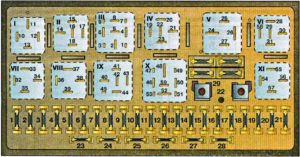
Audi 80 (B3) (1986 – 1991) – fuse box diagram
Year of production: 1986, 1987, 1988, 1989, 1990, 1991
Fuse Box
| No. |
Description |
A |
| 1 | Fog lights, rear fog light | 15 |
| 2 | Emergency flashers | 15 |
| 3 | Horn, brake lights | 25 |
| 4 | Reading lights, luggage compartment, cigar lighter, interior lights, make-up mirror, Board Computer, radio, clock, auto climate control, alarm system | 15 |
| 5 | Radiator cooling fan | 30 |
| 6 | Side marker, park lights, right | 5 |
| 7 | Side marker, park lights, left | 5 |
| 8 | Hi-beam headlight, right, hi-beam indicator light | 10 |
| 9 | Hi-beam headlight, left | 10 |
| 10 | Low beam headlight, right | 10 |
| 11 | Low beam headlight, left | 10 |
| 12 | Instrument cluster, back-up lights, Auto-Check, cruise control, ABS, Board Computer, differential locks, electronic thermoswitch, throttle valve time control unit, radiator cooling fan after-run control unit | 15 |
| 13 | Fuel pump, warm-up regulator | 15 |
| 14 | Glove compartment, engine compartment, license plate lights | 5 |
| 15 | Windshield wipers, thermoswitch, radiator cooling fan, turn signals, A/C pressure switch | 25 |
| 16 | Rear window heat element, outside mirror heat element | 30 |
| 17 | Fresh air blower, A/C | 30 |
| 18 | Power mirrors, rear window wiper (Coupe) | 5 |
| 19 | Central locking system, heated lock system | 10 |
| 20 | Radiator cooling fan (step 1), radiator cool fan after-run | 30 |
| 21 | Diagnostic | 10 |
| 21 | Rear cigar lighter | 25 |
| 22 | Not used | – |
| 23 | Power seats with memory, power seat control unit | 30 |
| 24 | Engine control I | 10 |
| 25 | Heated seats | 30 |
| 26 | Daytime driving lights (Canada) | 5 |
| 27 | Engine control I (from September, 1987) | 10 |
| 28 | Engine control II | 15 |
| 29 | Spare fuses | 15 |
| Relay | ||
| I | Fog lights, J5 | |
| II | up to 1990: Radiator cooling tan (stage 2), J101 from 1990: Not used |
|
| III | Radiator cooling fan after-run control unit, J138 | |
| IV | up to 1990: Not used from 1990: Headlight washer system, J39 |
|
| V | Load reduction relay, J18 | |
| VI | up to 1990: A/C fresh air blower, J11 from 1990: Radiator cooling fan high speed relay, J101 |
|
| VII | Horn, J4 | |
| VIII | Bridge between contact 36 and 38 for manual transmissions Auto transmission, J60 |
|
| IX | Intermittent washer/wiper, J31 | |
| X | Fuel pump, J17 | |
| XI | Radiator cooling fan (stage 1), J26 | |
Auxiliary relay panel
| No. | Description |
| 1 | ABS system, J156 |
| 2 | Seat belt, radio, parking light warning, J152 |
| 3 | Interior light control unit, J140 |
| 4 | A/C clutch control unit, J153 |
| 5 | Not used |
| 6 | Dynamic oil pressure warning (without Auto-Check), J114 Lamp control unit, front (with Auto-Check), J123 |
| 7 | Not used |
| 8 | Not used |
| 9 | Not used |
| 10 | Not used |
| 11 | Not used |
| 12 | Circuit breaker (power seats with memory, power windows, power sunroof), S43 |
| 13 | Seat heater control unit, passenger. J132 |
| 14 | Seat heater control unit, driver, J131 |
| 15 | Sunroof relay, J139 Sunroof and power window control unit, J139 |
| 16 | Sunroof and power window control unit, J139 |
| 17 | Wire distributor adaptor, (optional equipment connector) |
| 18 | Not used |
WARNING: Terminal and harness assignments for individual connectors will vary depending on vehicle equipment level, model, and market.


