Pontiac Firebird (1995) – fuse box diagram
Year of production: 1995
Instrument Panel Fuse Block
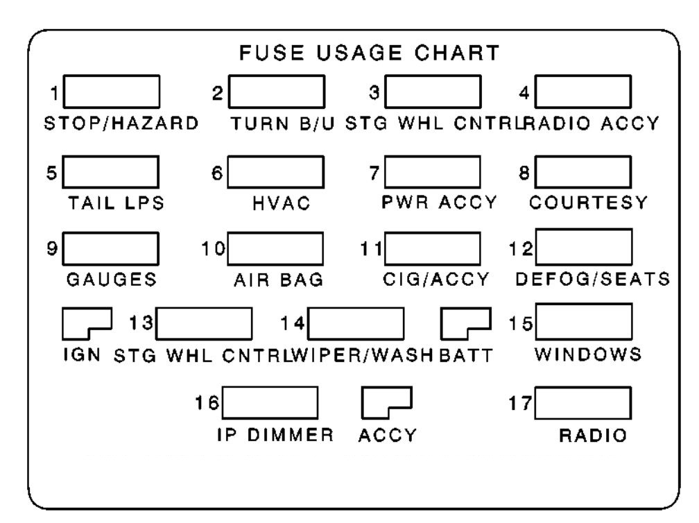
| Fuses | Usage | |
| 1 | AIR BAG | SIR Components |
| 2 | TURN B-U | Backup Lamps; Daytime Running Lamps Module (Canada);Turn Flasher; Transmission Range Switch; Traction Control Switch |
| 3 | HVAC | Heat Control Selector Switch (Heatedfir Conditioner); Rear Defogger |
| 4 | RADIO ACCY | Power Antenna; Disc Changer |
| 5 | PCM IGN | Powertrain Control Module; Fuel Pump Re1ay;Theft Deterrent Module; Engine Mass Air Flow Sensor (V8 Engine) |
| 6 | STOP/HAZARD | Brake Light/Cruise Release Switch; Hazard Flasher |
| 7 | PWR ACCY | Power Door Locks; Power Mirrors; Hatch Release Switch; Auxiliary Accessory Wir |
| 8 | COURTESY | Audio Alarm Module; Courtesy Lamps: Console Compartment, Glove Box, Dome, Trunk, Rear Courtesy, Rearview Mirror; Radio; Theft Deterrent Module; SECURITY Indicator; Hatch Release Relay; Keyless Entry Receiver |
| 9 | GAGES | Audio Alarm Module; Daytime Running Lamps Module (Canada); Diagnostic Energy Reserve Module; Instrument Cluster; Keyless Entry Receiver; Brake Switch Assembly; Auxiliary Accessory Wir |
| 10 | TAIL LTS | Exterior Lighting |
| 11 | CIGAR/HORN | Cigarette Lighter; Horn Relay; Data Link Connector |
| 12 | DEFOGBEATS | Power Seats; Rear Defogger |
| 13 | IP DIMMER | Brightness Control |
| 14 | WIPEWASH | Windshield Wipermasher |
| 15 | WINDOWS | Power Windows, Convertible Top Switch (Circuit Breaker); Cooling Level Latching Module |
| 16 | CRANK | Diagnostic Energy Reserve Module |
| 17 | RADIO | Radio Amplifier; Steering Wheel Controls |
Underhood Electrical Center
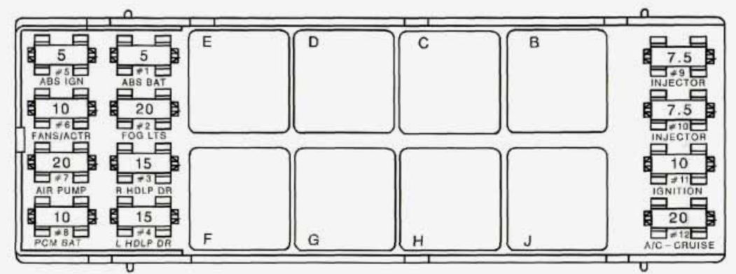
| Fuse | Ampere rating [A] | Usage | |
| 1 | ABS BAT | 5 | Electronic Brake Control Module |
| 2 | FOG LTS | 20 | Fog Lamps |
| 3 | R HDLP DR | 15 | Headlamp Doors Module |
| 4 | L HDLP DR | 15 | Headlamp Doors Module |
| 5 | ABS IGN | 5 | Anti-Lock Brake System |
| 6 | FANS/ACTR | 10 | Coolant Fan Relays; EVAP Canister Purge So1enoid;Exhaust Gas Recirculation; Reverse Lockout So1enoid;Skip Shift Solenoid; Heated Oxygen Sensors (V8 Engine) |
| 7 | AIR PUMP | 20 | Air Pump Relay |
| 8 | PCM | 10 | Powertrain Control Modul |
| 9 | INJECTOR | 7,5 | Fuel Injectors |
| 10 | INJECTOR | 7,5 | Fuel Injectors |
| 11 | IGNITION | 10 | VIN Engine Code S: Camshaft Position Sensor;Crankshaft Position Sensor; Ignition Control Modu1e;Automatic Transmission; Ignition Coil (V-8 Engine); Ignition Coil Module (V-8 Engine) |
| 12 | A/C-CRUISE | 20 | Air Conditioning Compressor Relay; Cruise Control Switches and Module |
| Relay | Usage |
| B | Air Conditioning Compressor |
| C | Anti-Lock Brake Systedm |
| D | Coolant Fan Number 1 |
| E | AIR Pump |
| F | Coolant Fan Number 2 |
| G | Traction Control System |
| H | Fog Lamps |
| J | Cooling Fan Number 3 |
WARNING: Terminal and harness assignments for individual connectors will vary depending on vehicle equipment level, model, and market.