
Nissan Navara (1997 – 2004) – fuse box diagram
Year of production: 2003, 2004, 2005, 2006, 2007, 2008, 2009, 2010
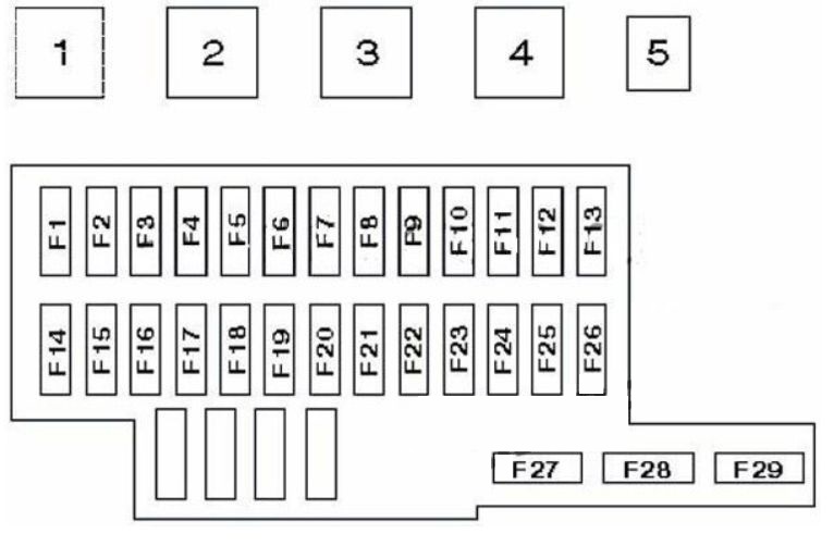
Passenger Compartment Fuse Box
Located on the right side of the glove box, behind the protective cover.
| № | A | Component |
|---|---|---|
| 1 | Relay 1 main ignition circuits | |
| 2 | Auxiliary Ignition Circuit Relay | |
| 3 | Relay 2 main ignition circuits | |
| 4 | The power windows relay | |
| 5 | Thermal fuse (central locking) | |
| F1 | 20A | (20A) Rear window defogger |
| F2 | 10A | (10A) Anti-lock Braking System (ABS), brake lights |
| F3 | 10A | (10A) Interior lighting lamps, fog lamp (s) |
| F4 | – | – |
| F5 | 10A | (10A) Turn lights / alarms |
| F6 | 10A | (10A) Air conditioning, anti-theft system, audio antenna, automatic transmission control system, clock, diagnostic connector, immobilizer, instrument cluster, central locking remote control system, car speed sensor |
| F7 | 10A | (10A) Audio system, audio antenna |
| F8 | 10A | (10A) Seat heater |
| F9 | – | – |
| F10 | 10A | (10A) Turn lights / alarms |
| F11 | 10A | (10A) SRS (airbag) system, automatic transmission control system, charging system, daytime running light, engine management system malfunction indicator glow plug, immobilizer, instrument cluster, meters / indicators, reversing lights, car speed sensor, indicators |
| F12 | 10A | (10A) ABS system, audible warning / buzzer, automatic transmission control system, diagnostic connector, daytime running light, low headlights / high beams, power windows, engine warm-up switch, door mirror heater, rear window defogger, central locking remote control system |
| F13 | 10A | (10A) Additional idle air control valve (some models), air conditioning system, cooling fan relay |
| F14 | – | – |
| F15 | 15A | (15) Heater / air conditioning |
| F16 | 15A | (15) Heater / air conditioning |
| F17 | 15A | (1 5A) Cigarette lighter |
| F18 | 20A | (20A) Headlight washers |
| F19 | 10A | (10A) Heated door mirror heater |
| F20 | 10A | (10A) Daytime running light, electronic engine control unit (start signal) |
| F21 | 10A | (10A) Engine management system, immobilizer |
| F22 | 15A | (15A) Engine management system, fuel pump relay |
| F23 | 15A | (15A) Engine Management System (ZD30) |
| F24 | 10A | (10A) Airbag |
| F25 | 10A | (10A) Engine management |
| F26 | 20A | (20A) Windscreen wiper / washer |
| F27 | 10A | (10A) Audible warning / buzzer, headlight corrector, front / rear (left), left license plate light, backlighting of switches |
| F28 | 10A | (10A) Front / rear dimensions (right), right license plate light |
| F29 | – | – |
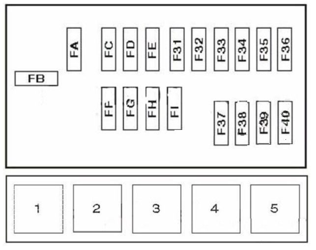
Engine compartment fuse panel
The fuse box is located in the engine compartment (right-side).
| № | A | Component |
|---|---|---|
| FA | 80A/100A | Battery power distribution (80A-petrol, 100A-Diesel) |
| FB | 60A/80A | Glow plugs (60A-YD engine, 80A-except YD engine) |
| FC | 40A | Central locking, power windows |
| FD | 30A | Cooling fan motor |
| FE | – | – |
| FF | 40A | Ignition switch |
| FG | 30A | Anti-lock Braking System (ABS) |
| FH | 30A | Anti-lock Braking System (ABS) |
| FI | 30A | Combination switch, daytime running lights |
| F31 | 10A | Charging system |
| F32 | 10A | Horn(s) |
| F33 | 10A | Engine management system, immobilizer (petrol) |
| F34 | – | – |
| F35 | 10A | Engine Management System (Diesel) |
| F36 | 20A | Engine management system, immobilizer (Diesel) |
| F37 | 15A | Combination switch, daytime running light, low beam / high beam, headlights, fog light (s) |
| F38 | 15A | Combination switch, daytime running light, low beam / high beam, headlights |
| F39 | 10A | Audio system |
| F40 | 15A | Fog lights (some models) |
| Relay | ||
| 1 | Cooling Fan Relay | |
| 2 | Relay of the electromagnetic clutch of the A/C compressor | |
| 3 | Horn relay | |
| 4 | Start inhibit relay (“P” / “N”) | |
| 5 | Engine control system relay | |
WARNING: Terminal and harness assignments for individual connectors will vary depending on vehicle equipment level, model, and market