BMW 3 Series E36 and E35/5 (1990 – 2000) – fuse box diagram
Years: 1990, 1991, 1992, 1993 ,1994, 1995,
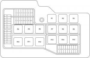
Front power distribution box
| Fuse | Ampere rating [A] | Description |
| 1 | 30 | Power tilt/slide sunroof (SHD) |
| 2 | 15 | as of 9/93: Trailer coupling |
| 5 | as of 9/96: Engine control system | |
| 3 | 30 | Rear wipe/wash interval control unit (Touring, Compact) Headlight washer system (SRA) Radio/HiFi (9/94 to 8/95) |
| 4 | 15 | Unloader relay terminal 15 (Heated seats) |
| 5 | 30 | Passenger’s seat adjustment switch |
| 6 | 20 | Rear defogger relay |
| 30 | Rear defogger relay | |
| 7 | 5 | Electronic gear indicator Central locking switch Driver’s door lock switch Central locking (ZV) drive driver’s door Central locking module (ZVM) Central locking (ZV) drive passenger’s door Passenger’s door lock switch Control unit, remote control Rear lid lock relay Central locking drive rear lid (Touring) Rear lid microswitch (mechanical convertible soft top) Convertible soft top flap lock Convertible soft top module Anti-theft control module (Alpine) |
| 8 | 15 | Horn relay Anti-theft control module (Alpine) |
| 9 | 20 | Radio Hifi amplifier Subwoofer CD changer (to 8/93) Unloader relay terminal R (to 8/92) |
| 10 | 30 | Antilock brake system (ABS) Automatic stability control (ASC) |
| 11 | 7,5 | without CCM: Left low beam light with CCM: Check control module |
| 12 | 7,5 | without CCM: Right low beam light with CCM: Check control module |
| 13 | 5 | Comfort relay (two–door model) |
| 14 | 30 | Driver’s side power window module (to 8/93) Passenger’s side power window module (to 8/93) ZKE control unit (ZKE IV; as of 9/93) |
| 15 | 15 | Left fog light Right fog light Instrument cluster |
| 7,5 | Left fog light Right fog light Instrument cluster |
|
| 16 | 5 | A/C compressor relay Auxiliary fan stage 1 relay (normal speed relay) Auxiliary fan stage 2 relay (high speed relay) |
| 17 | 10 | without CCM: Fog light switch (Rear fog light switch) |
| 7,5 | with CCM: Fog light switch (Rear fog light switch) | |
| 18 | 15 | Fuel pump |
| 19 | 15 | to 8/92: Park heating/ventilation relay box |
| 30 | as of 8/93: Relay module | |
| 20 | 30 | to 8/92: Blower switch as of 9/92: without park ventilation: Heating blower relay with park ventilation: Heating blower relay Independent ventilation relay |
| 21 | 5 | Antilock brake system (ABS) Automatic stability control (ASC) |
| 22 | 5 | Light switch Daytime running lights coding diode |
| 23 | 5 | Combination switch (turn indicator/low beam selector) Instrument cluster Thermal switch (LA Japan) ABS control unit Rear defogger relay Multi–function clock / On–board display / On–board computer Unloader relay terminal 15 with IHKA: Automatic climate control unit with heating control: Water valves Temperature regulator |
| 24 | 10 | Thermal switch, heated jets Rollover sensor Mirror control unit Parking aid control unit |
| 25 | 5 | Light switch Day light relay module (as of 9/97) High beam relay (9/94 to 8/97) Low beam relay (9/92 to 8/94) Left park light relay (9/93 to 8/94) Right park light/license plate light relay (9/93 to 8/94) |
| 26 | 15 | to 8/92: Program switch Auxiliary connector (US) Automatic transmission range switch Diagnostic connector Reversing light switch (without EGS) |
| 10 | as of 9/92: Automatic transmission range switch Program switch Fuel heating (diesel) Alternator cut–out relay (diesel) Diagnostic connector Oil level switch, thermal Oxygen sensor and air pump relays Reversing light switch SMG control unit Hydraulic pump relay Hydraulic unit Starter immobilization relay Throttle flap heater |
|
| 27 | 5 | Instrument cluster |
| 28 | 5 | with EGS: Automatic transmission range switch with SMG: SMG control unit Electronic gear indicator Gear indicator, centre console |
| 29 | 7,5 | Left high beam |
| 30 | 7,5 | Right high beam |
| 31 | 5 | Instrument cluster On–board display / Multi–function clock On–board computer Analogue clock Chime module Electronic immobiliser control unit (EWS II; as of 9/94) Antitheft (DWA) LED With IHKA: Water valves Automatic climate control unit With IHKR: IHKR control panel Integrated climate regulation control module |
| 32 | 30 | Front cigar lighter Reading lights relay |
| 33 | 10 | Ignition switch (as of 9/93) Charge socket Light switch CD changer (as of 9/93) Cellular telephone Door lock heating relay Luggage compartment light Rear compartment interior light, centre (Touring) Right trunk light assembly (Compact) Interior light, right rear (with reading light) Interior light, left rear (with reading light) Interior/reading lamp, front (with ZKE) ZKE control unit (as of 9/93) Front left footwell light (Front right footwell light) Left parking light relay Driver’s side power window module (to 8/93) |
| 34 | 15 | Hazard flasher relay Crash alarm sensor (with crash alarm sensor) |
| 35 | 25 | with ZVM: Central locking module (ZVM) with ZKE: ZKE control unit |
| 36 | 30 | Wipe–wash module (Low II) / Wipe/wash module |
| 37 | 10 | Light switch Right parking light/licence plate light relay |
| 38 | 30 | Antilock brake system (ABS) Automatic stability control (ASC) |
| 39 | 7,5 | A/C compressor relay |
| 40 | 30 | Driver’s seat adjustment switch Driver’s lumbar support switch |
| 41 | 30 | Auxiliary fan stage 1 relay (low; only diesel) Auxiliary fan stage 2 relay (high) |
| 42 | 7,5 | Electronic seat control Driver’s side impact sensor Passenger’s side impact sensor Rollover sensor Airbag diagnostic module Driver’s seat belt buckle switch |
| 43 | 5 | Interior light, right rear Interior light, left rear Top Hifi switch Central locking module (ZVM) ZKE control unit Spatial sound relay Passenger’s make–up mirror light Driver’s make–up mirror light Interior/reading lamp, front Convertible soft top module Control unit, remote control Cellular telephone Reading lights relay Anti-theft control module (Alpine) |
| 44 | 15 | Wipe–wash module (Low II) Wipe/wash module Rear wipe/wash interval control unit (Touring, Compact) Windscreen wiper switch (Touring, Compact) Radio Glovebox light/switch Twin relay module (up to 8/95) Unloader relay terminal R (up to 8/92) |
| 45 | 7,5 | Check control module Transmit/receive module (EWS II; as of 9/95) Starter immobilization switch (as of 9/96) On–board computer / Multi–function clock / On–board display Wiper relay (up to 8/95) Wiper motor relay (up to 8/95) |
| 46 | 15 | Clutch switch Instrument cluster Brake light switch Cruise control module Cruise control switch Data link connector (as of 9/95) Board computer (BC-low) |
| Relay | ||
| R1 | Fuel pump relay | |
| Oxygen sensor and air pump relays (M3) | ||
| Secondary air pump relay | ||
| Engine control module relay | ||
| Alternator cut–out relay (diesel) | ||
| R2 | Engine control module relay | |
| Fuel pump relay | ||
| R3 | Oxygen sensor relay | |
| EKP and start detector relay | ||
| Wiper motor relay | ||
| Engine control module relay | ||
| Secondary air pump relay | ||
| Delivery pump relay (diesel) | ||
| R4 | Horn relay | |
| R5 | Fog light relay | |
| R6 | High beam relay (to 8/93) | |
| Low beam relay (as of 9/93) | ||
| R7 | Low beam relay (to 8/93) | |
| High beam relay (as of 9/93) | ||
| Secondary air pump relay | ||
| R8 | Hazard flasher relay | |
| R9 | Blower relay | |
| R10 | Rear defogger relay | |
| R11 | ABS relay | |
| R12 | ABS pump motor relay | |
| ABS pump motor relay, timed | ||
| R13 | Auxiliary fan stage 2 relay (high speed) | |
| R14 | A/C compressor relay | |
| R15 | Auxiliary fan stage 1 relay (low speed) | |
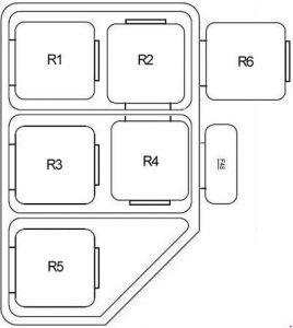
Relay carrier under LH side of dash
| Fuse | Ampere rating [A] | Description |
| 48 | 40 | Auxiliary fan stage 2 relay (high speed) |
| 50 | 5 | Exhaust gas flap valve Carbon canister valve |
| Relay | ||
| R1 | Independent ventilation relay | |
| R2 | Twin relay (up to 8/95) | |
| R3 | Crash alarm sensor | |
| R4 | Headlight/foglight cleaning module (SRA) (up to 8/95) | |
| High beam relay | ||
| Day running ligth relay | ||
| R5 | Comfort relay | |
| Folding sunroof comfort relay | ||
| R6 | Unloader relay terminal R (up to 8/92) | |
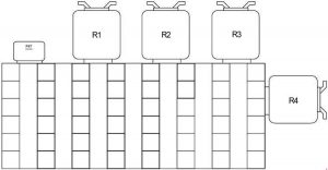
Connector strip under LH side of dash
| Fuse | Ampere rating [A] | Description |
| 47 | 158 | Horn relay (Alpine) On-board computer Anti-theft control module (Alpine) |
| Relay | ||
| R1 | Unloader relay terminal 15 | |
| Horn relay (Compact) | ||
| R2 | Rear lights relay | |
| Wiper relay (up to 8/95) | ||
| R3 | Wiper motor relay (up to 8/95) | |
| R4 | Hinged window relay | |
| Starter relay (up to 8/94) | ||
| Starter immobilization relay (9/93 to 9/94) | ||
Connector strip under RH side of dash
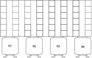
| Number | Realy |
| R1 | Right parking light/licence plate light relay |
| R2 | Left parking light relay |
| Thermal switch (LA Japan) | |
| R3 | Door lock heating relay |
| R4 | Rear window blower relayWARNING: Terminal and harness assignments for individual connectors will vary depending on vehicle equipment level, model, and market. |
WARNING: Terminal and harness assignments for individual connectors will vary depending on vehicle equipment level, model, and market.

