
Kubota L4600 – fuse box diagram
Year of production:
Fuse box
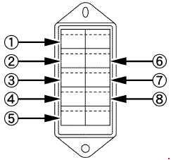
| Number | Ampere ratting [A] | Protected circuit |
| 1 | 15 | Alternator |
| 2 | 5 | Head lights |
| 3 | 5 | Hazard |
| 4 | 15 | Panel |
| 5 | 5 | T/M Controller 1 |
| 6 | 5 | Work light |
| 7 | 10 | Brake lamp switch |
| 8 | 10 | T/M Controller 2 |
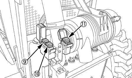
| Number | Ampere ratting [A] | Protected circuit |
| 9 | 50 | Key stop |
| 10 | 40 | Starter relay |
| 11 | 40 | Dome lamp |
WARNING: Terminal and harness assignments for individual connectors will vary depending on vehicle equipment level, model, and market.