Volvo V40 (2013) – fuse box diagram
Year of production: 2013
Engine compartment fuses box
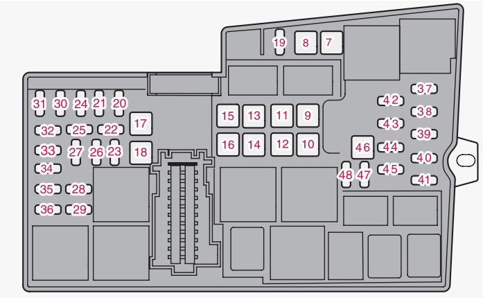
| Fuse/Relay Location | [A] | Description |
| 7 | 40 | ABS pump |
| 8 | 30 | ABS valves |
| 9 | 20 | Headlamp washers* |
| 10 | 40 | Ventilation fan |
| 11 | — | — |
| 12 | 30 | Primary fuse for fuses 32-36 |
| 13 | 30 | Starter motor actuator solenoid (not Start/Stop) |
| 14 | 40 | Electric windscreen, right side* |
| 15 | — | — |
| 16 | 40 | Electric windscreen, left side* |
| 17 | 20 | Parking heater* |
| 18 | 20 | Windscreen wipers |
| 19 | 5 | Central electronic module, reference voltage, standby battery (Start/Stop) |
| 20 | 15 | Horn |
| 21 | 5 | Brake light |
| 22 | — | — |
| 23 | 5 | Headlamp control |
| 24 | 5 | Internal relay coils |
| 25 | 15 | 12 V socket, tunnel console front |
| 26 | 15 | Transmission control module |
| 27 | 15 | Solenoid clutch A/C |
| 28 | 15 | 12 V socket, tunnel console rear |
| 29 | 10 | Climate sensor*; air intake throttle motors |
| 30 | 5 | Engine control module (5-cyl.) |
| 31 | 20 | Power seat, right* |
| 32 | 10 | Relay coil in cooling fan relay (4- cyl., 5-cyl. diesel); Lambdasonds (4-cyl. petrol); Mass air flow meter (diesel), Bypass valve, EGR cooling (diesel); Regulator valve, fuel flow (5-cyl. diesel); Regulator valve, fuel pressure (5-cyl. diesel) |
| 20 | Relay coil in cooling fan relay (5-cyl. petrol); Lambda-sonds (5-cyl. petrol) | |
| 33 | 10 | Mass air flow meter (4-cyl. petrol); EVAP valve (4-cyl. petrol); Injection valves (5-cyl. petrol); Control motor, turbo (4-cyl. diesel); Regulator valve, fuel flow (4-cyl. diesel); Solenoid, piston cooling (5-cyl. diesel); Turbo regulator valve (5-cyl. diesel); Oil level sensor (5-cyl. diesel) |
| 34 | 10 | Valves (petrol); Solenoids (petrol); Lambda probe (diesel); Crankcase ventilation heater (5-cyl.); Mass air flow meter (5-cyl. petrol) |
| 35 | 10 | Ignition coils (petrol) |
| 15 | Diesel filter heater; Glow plug control unit (5-cyl. diesel); Oil pump, automatic gearbox (5-cyl. diesel Start/Stop) |
|
| 36 | 10 | Engine control module (4-cyl.) |
| 15 | Engine control module (5-cyl.); Throttle unit (5-cyl. petrol) | |
| 37 | 5 | ABS |
| 38 | 10 | Engine control module; Transmission control module; Airbags |
| 39 | 10 | Light height control* |
| 40 | 5 | Electric control servo |
| 41 | 15 | Central electronic module |
| 42 | — | — |
| 43 | 10 | Coolant pump (Start/Stop) |
| 44 | 5 | Collision warning system |
| 45 | 5 | Accelerator pedal sensor |
| 46 | — | Charging point, standby battery |
| 47 | — | — |
| 48 | — | — |
Under the glovebox
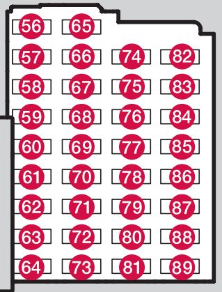
| Fuse/Relay | [A] | Description |
| 56 | 20 | Fuel pump |
| 57 | — | — |
| 58 | 15 | Rear window wiper |
| 59 | 5 | Reserve position, interior lighting |
| 60 | 10 | Interior lighting; Power seats |
| 61 | 10 | Blind, glass roof* |
| 62 | 5 | Rain sensor*; Dimming, interior rearview mirror*; Moisture sensor* |
| 63 | 5 | Collision warning system* |
| 64 | — | — |
| 65 | 10 | Unlocking, tailgateA |
| 66 | — | — |
| 67 | 5 | Reserve position 3, constant voltage |
| 68 | 15 | Steering lock |
| 69 | 5 | Combined instrument panel |
| 70 | 10 | Central locking system, fuel filler flap (B) |
| 71 | 10 | Climate panel |
| 72 | 7,5 | Steering wheel module |
| 73 | 5 | Siren alarm*; Data link connector OBDII |
| 74 | 15 | Main beam |
| 75 | — | — |
| 76 | 10 | Reversing lamp |
| 77 | 20 | Windscreen wipers (C); Rear windscreen wiper |
| 78 | 5 | Immobiliser |
| 79 | 15 | Reserve position 1, constant voltage |
| 80 | 20 | Reserve position 2, constant voltage |
| 81 | 5 | Movement sensor alarm*; Remote receiver |
| 82 | 20 | Windscreen wipers (D); Rear windscreen wiper |
| 83 | 10 | Central locking system, fuel filler flap (E) |
| 84 | 10 | Unlocking, tailgate (F) |
| 85 | 7,5 | PTC element, air preheater*; Button, rear seat heating* |
| 86 | 10 | Airbags; Pedestrian airbag |
| 87 | 7,5 | Reserve position 4, constant voltage |
| 88 | — | — |
| 89 | — | — |
| A See also fuse 84 B See also fuse 83 C See also fuse 82 D See also fuse 77 E See also fuse 70 F See also fuse 65 |
||
Below right front seat
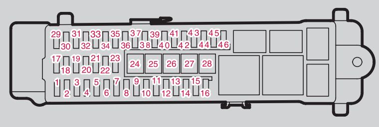
| Fuse/Relay | [A] | Description |
| 1 | — | — |
| 2 | 10 | Keyless* |
| 3 | 5 | Door handle (Keyless*) |
| 4 | 25 | Control panel, left front door |
| 5 | 25 | Control panel, right front door |
| 6 | 25 | Control panel, left rear door |
| 7 | 25 | Control panel, right rear door |
| 8 | — | — |
| 9 | 20 | Power seat left* |
| 10 | — | — |
| 11 | — | — |
| 12 | 5 | Audio control unit (amplifier)* |
| 13 | — | — |
| 14 | 5 | Telematics*; Bluetooth* |
| 15 | 15 | Audio; Infotainment control unit |
| 16 | 10 | Digital radio*; TV* |
| 17 | 15 | 12 V socket, cargo area |
| 18 | — | — |
| 19 | — | — |
| 20 | — | — |
| 21 | — | — |
| 22 | — | — |
| 23 | 20 | Trailer socket 2* |
| 24 | 40 | Primary fuse for fuses 12-16: Infotainment |
| 25 | — | — |
| 26 | 40 | Trailer socket 1* |
| 27 | 30 | Rear window defroster |
| 28 | — | — |
| 29 | 5 | BLIS* |
| 30 | 5 | Parking assistance* |
| 31 | 5 | Parking camera* |
| 32 | — | — |
| 33 | — | — |
| 34 | 15 | Seat heating (driver’s side) |
| 35 | 15 | Seat heating (passenger side) |
| 36 | — | — |
| 37 | — | — |
| 38 | — | — |
| 39 | 15 | Seat heating, rear right* |
| 40 | 15 | Seat heating, rear left* |
| 41 | 15 | AWD control module* |
| 42 | — | — |
| 43 | — | — |
| 44 | — | — |
| 45 | — | — |
| 46 | — | — |
WARNING: Terminal and harness assignments for individual connectors will vary depending on vehicle equipment level, model, and market.