Suzuki Kizashi (2010) – fuse box diagram
Year of production: 2010
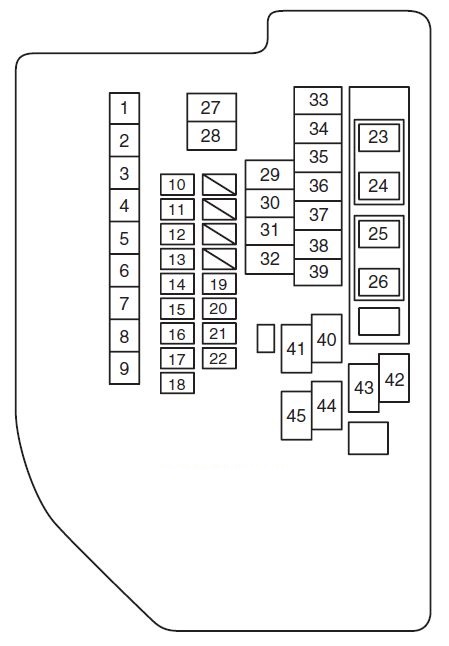
Fuses in the Engine Compartment
Suzuki Kizashi – fuse box diagram – engine compartment
No. A Circuit Protected
1
50
Ignition switch
2
30
Radiator fan sub
3
30
Radiator fan main
4
30
Starting motor
5
40
Light
6
40
ESP control module
7
50
Keyless start control module
8
50
Power window, Power seat
9
50
Blower fan
10
10
Air conditioning compressor
11
15
Door mirror heater
12
15
Throttle motor
13
30
Rear defogger
14
30
—
15
7,5
Head light
16
20
Fuel injection
17
25
ESP control module
18
25
Back up
19
15
Head light low (Left)
20
15
Head light low (Right)
21
15
Head light high (Left)
22
15
Head light high (Right)
23
15
CVT
24
20
Front fog light
25
15
O2 sensor heater
26
15
Horn
27
—
Head light low relay (Left)
28
—
Head light low relay (Right)
29
—
—
30
—
—
31
—
—
32
—
Air conditioning compressor relay
33
—
Rear defogger relay
35
—
Windshield wiper relay 2
36
—
—
37
—
Windshield wiper relay 1
38
—
Starting motor relay
39
—
Fuel pump relay
40
—
Radiator fan relay 3
41
—
Radiator fan relay 1
42
—
Door mirror heater relay
43
—
Radiator fan relay 2
44
—
Main relay
45
—
Throttle motor relay
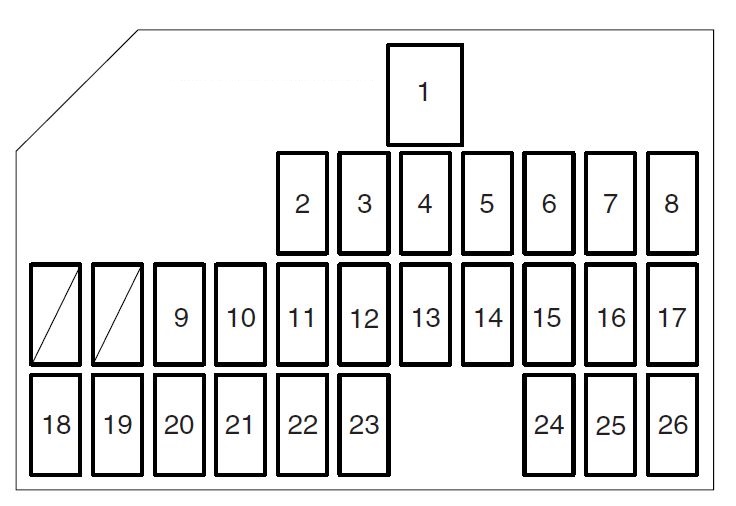
Fuses under the Dash Board
Driver’s side
Suzuki Kizashi – fuse box diagram – dashboard (driver’s side)
No. A Circuit Protected
1
30
Power window
2
15
Windshield washer motor
3
20
Seat heater
4
25
Windshield wiper motor
5
7,5
IG2 SIG
6
15
Ignition coil
7
15
Accessory 2
8
15
Accessory
9
10
ESP control module
10
7,5
Cruise control
11
7,5
IG1 SIG
12
7,5
—
13
7,5
Meter
14
10
Back-up light
15
10
Air bag
16
15
Steering lock
17
7,5
BCM
18
20
Sunroof
19
7,5
—
20
10
Tail light
21
10
Brake light
22
10
Hazard
23
20
Front power window (Left)
24
15
Radio
25
10
Dome light
26
20
Door lock
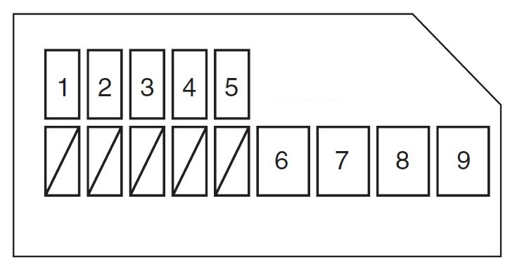
Passenger’s side
Suzuki Kizashi – fuse box diagram – dashboard (passenger’s side)
No. A Circuit Protected
1
20
Rear power window (Right)
2
20
Rear power window (Left)
3
20
Front power window (Right)
4
15
4WD
5
20
Battery fan
6
20
Audio
7
30
Power seat (Right)
8
30
Power seat (Left)
9
30
Blank
WARNING: Terminal and harness assignments for individual connectors will vary depending on vehicle equipment level, model, and market.