Skoda Yeti (2017) – fuse box diagram
Year of production: 2017
Fuse box in dash panel
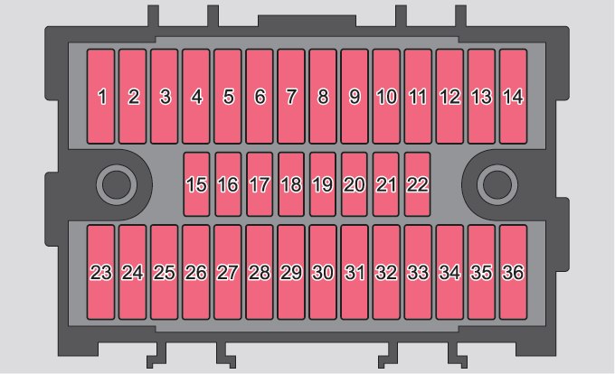
| Number | Power consumer |
| 1 | Heating of the gearbox vent (diesel engine), Automatic gearbox |
| 2 | Towing hitch – left light |
| 3 | Towing hitch – right light |
| 4 | Instrument cluster, windshield wiper lever, turn signal light lever, camera |
| 5 | Air blower for heating, radiator fan, air conditioning system, Climatronic |
| 6 | Rear window wiper |
| 7 | Emergency call |
| 8 | Towing hitch – contact in the socket |
| 9 | Interior lighting, rear fog light |
| 10 | Rain sensor, light switch, diagnostic socket |
| 11 | Left side cornering lights |
| 12 | Right side cornering lights |
| 13 | Radio |
| 14 | Central control system, engine management system |
| 15 | Light switch |
| 16 | All-wheel drive |
| 17 | KESSY, steering lock |
| 18 | Diagnostic connector, engine control system, brake sensor, fourwheel drive, START-STOP |
| 19 | ABS, ESP, switch for tyre air pressure control, parking aid, switch for OFF ROAD mode, START STOP button |
| 20 | Airbag |
| 21 | Variable Service Interval – WIV, reversing lamps, dimmable mirrors, pressure sensor, telephone preparation, air mass meter, headlamp levelling and swivelling headlights |
| 22 | Instrument cluster, electromechanical power steering, databus |
| 23 | Central locking, boot lid |
| 24 | Electric windows – Rear |
| 25 | Rear window heater, auxiliary heating and ventilation |
| 26 | Power socket in the boot |
| 27 | Panoramic tilt / slide sunroof, electric operation of sun blinds |
| 28 | Fuel pump, injectors, AdBlue® heating |
| 29 | Electric windows – front, outside mirror – Heating, fold-in function, Adjusting the mirror surface |
| 30 | 12 volt power outlet – front and rear |
| 31 | Headlight cleaning system |
| 32 | Heated front seats |
| 33 | Heating, air conditioning, Climatronic, remote control for auxiliary heating |
| 34 | Car alarm, reserve horn |
| 35 | Automatic gearbox |
| 36 | Tow hitch |
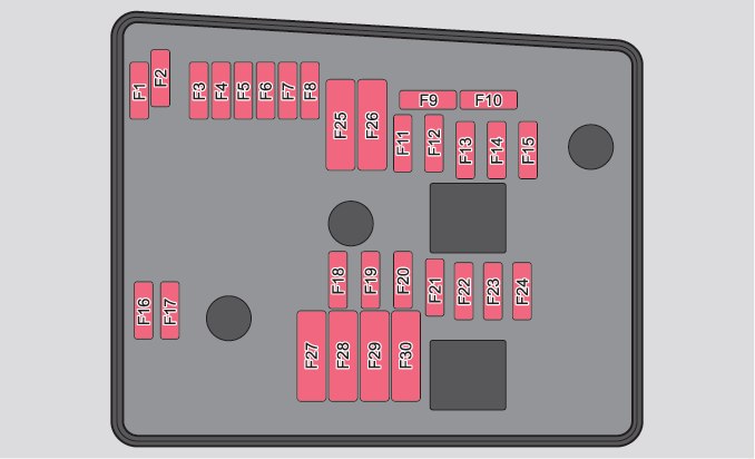
Fuse box in engine compartment
| Number | Power consumer |
| F1 | Not assigned |
| F2 | Automatic gearbox, AdBlue control system |
| F3 | Battery data module |
| F4 | ABS |
| F5 | Automatic gearbox |
| F6 | Not assigned |
| F7 | Power suppy terminal 15, Starter |
| F8 | Radio, instrument cluster, telephone |
| F9 | Not assigned |
| F10 | Engine control unit |
| F11 | Auxiliary heating and ventilation |
| F12 | Databus |
| F13 | Engine control unit |
| F14 | Ignition |
| F15 | Lambda probe, fuel pump Glow plug system |
| F16 | Right headlight, right taillight |
| F17 | Horn |
| F18 | Music amplifier |
| F19 | Windscreen wipers |
| F20 | Control valve for fuel pressure, high pressure pump |
| F21 | Lambda probe |
| F22 | Clutch pedal switch, brake pedal switch |
| F23 | Coolant pump Solenoid valve for charge pressure control, change-over valve for cooler High-pressure fuel pump |
| F24 | Active charcoal filter, exhaust gas recirculation valve, radiator fan |
| F25 | ABS |
| F26 | Left front headlight, left taillight |
| F27 | Glow plug system |
| F28 | Windscreen heater |
| F29 | Power to the internal fuse carrier (fuses no. 24,27,31,32), electrically adjustable seats |
| F30 | Terminal Xa) |
| a) In order not to drain the battery unnecessarily when starting the engine, the electrical components of this terminal are automatically switched off. | |
WARNING: Terminal and harness assignments for individual connectors will vary depending on vehicle equipment level, model, and market.