Skoda Superb (2017) – fuse box diagram
Year of production: 2017
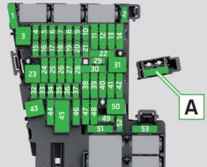
Fuse box in dash panel


| Number | Power consumer |
| 1 | Not assigned |
| 2 | Not assigned |
| 3 | Voltage stabilizer for taxi vehicles |
| 4 | Heated steering wheel |
| 5 | Databus |
| 6 | Automatic gearbox |
| 7 | Air conditioning, heating, receiver for the remote control for the auxiliary heating, heated rear window, heated windscreen, clock |
| 8 | Light switch, rain sensor, diagnostic connector, parking brake, lighting of the instrument cluster, sensor for the alarm system |
| 9 | USB socket |
| 10 | Infotainment screen, TV tuner, ExBoxM2 (applies to South Korea) |
| 11 | Left side belt tensioner |
| 12 | Infotainment |
| 13 | Shock absorber setting |
| 14 | Air blower for air conditioning, heating |
| 15 | Electric steering lock |
| 16 | Phonebox |
| 17 | Instrument cluster, emergency call |
| 18 | Reversing camera |
| 19 | KESSY |
| 20 | SCR |
| 21 | Haldex clutch, air conditioning compressor (Green Line) |
| 22 | Towing hitch |
| 23 | Light – right |
| 24 | Panoramic tilting / sliding sunroof |
| 25 | Central locking – driver’s door and rear left door, exterior mirror driver’s side – heating, fold-in function, setting the mirror surface |
| 26 | Heated front seats |
| 27 | Music amplifier |
| 28 | Towing hitch – contact in the socket |
| 29 | Operating lever underneath the steering wheel |
| 30 | 12-volt socket in luggage compartment |
| 31 | Light – left |
| 32 | Parking aid (Park Assist) |
| 33 | Airbag switch for hazard warning lights |
| 34 | TCS, ESC, Tyre Pressure Loss Indicator, air conditioning, reversing light switch, mirror with automatic blackout, START-STOP, heated rear seats, parking brake, light switch |
| 35 | AFS headlights, diagnostic connector, camera, radar, voltage stabilizer for taxi vehicles |
| 36 | Headlight right |
| 37 | Headlight left |
| 38 | Towing hitch – contact in the socket |
| 39 | Central locking – front passenger door and right rear door, front passenger side mirrors – heating, fold-in function, setting the mirror surface |
| 40 | 12-volt power outlet |
| 41 | Right side belt tensioner |
| 42 | Boot lid, headlight washers, windscreen washer system |
| 43 | Xenon headlights, ambient lighting |
| 44 | Trailer device – electrical outlet |
| 45 | Electrically adjustable seats |
| 46 | 230-Volt power socket |
| 47 | Rear window wiper |
| 48 | Blind spot detection |
| 49 | Coil on starter relay, clutch pedal switch |
| 50 | Opening the boot lid |
| 51 | Heating of the rear seats |
| 52 | Heated front seats |
| 53 | Heated rear window |
| A | Multifunctional unit for taxi vehicles – LHD |
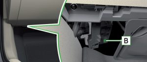
| B | Multifunctional unit for taxi vehicles – RHD |
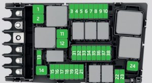
Fuse box in engine compartment

| Number | Power consumer |
| 1 | ESC, parking brake |
| 2 | ESC |
| 3 | Engine control unit |
| 4 | Radiator fan, control valve for fuel pressure, relay for electric auxiliary heater |
| 5 | Ignition |
| 6 | Brake sensor |
| 7 | Radiator shutters, coolant pump |
| 8 | Lambda probe |
| 9 | Coolant pump, ignition coil, preheating unit, air flow meter |
| 10 | Fuel pump |
| 11 | Electrical auxiliary heating system |
| 12 | Electrical auxiliary heating system |
| 13 | Automatic gearbox |
| 14 | Heated windscreen |
| 15 | Horn |
| 16 | Ignition |
| 17 | ESC, engine control unit, main relay coil |
| 18 | Databus, battery data module |
| 19 | Windscreen wipers |
| 20 | Anti-theft alarm |
| 21 | Not assigned |
| 22 | Engine control system, voltage stabilizer for taxi vehicles |
| 23 | Starter |
| 24 | Electrical auxiliary heating system |
| 31 | Not assigned |
| 32 | Not assigned |
| 33 | SCR |
| 34 | Not assigned |
| 35 | Not assigned |
| 36 | Not assigned |
| 37 | Auxiliary heating |
| 38 | Not assigned |
WARNING: Terminal and harness assignments for individual connectors will vary depending on vehicle equipment level, model, and market.


