
Peugeot 307 SW (2004) – fuse box diagram
Year of production: 2004
Instrument panel fuses
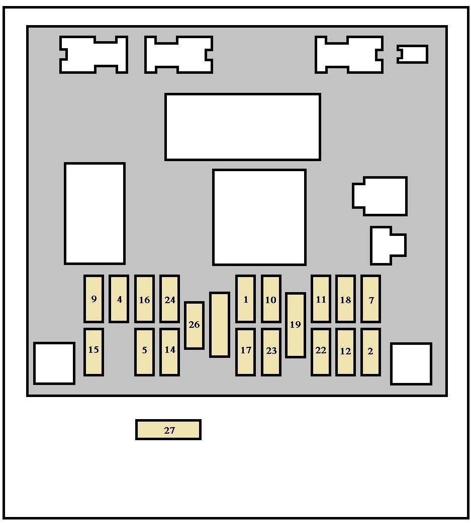
| Fuse | Ampere rating [A] | Functions |
| 1 | 10 | Rear fog lamp |
| 2 | 15 | Rear screen wiper |
| 4 | 15 | Front electric windows |
| 5 | 15 | Left brake light including trailer |
| 7 | 30 | Rear courtesy light, front courtesy light, map readers – 12V front socket – Glove box lighting – Sunroof shutter |
| 9 | 30 | Front electric windows – Press operation electric windows (incompatible with non-press operation electric windows) – Sunroof shutter |
| 10 | 15 | Diagnostic plug – 12 volts rear socket – trailer |
| 11 | 20 | Audio equipment – Multifunction displays – Steering wheel controls – Automatic gearbox |
| 12 | 10 | Front right side light, rear right side light – Number plate and trailer lighting – Central locking switch lights/ alarm//hazard warning lights – Air conditioning/ashtray light – Automatic gearbox switch lights – Lighter |
| 14 | 30 | Door opening/closing controls – Deadlocking controls |
| 15 | 30 | Press operation electric rear windows |
| 16 | 10 | Engine fuse box – Alarm – Particulate emission filter – Steering wheel controls – Air bags |
| 17 | 10 | Rear right brake light, 3rd brake light |
| 18 | 10 | Diagnostic plug – Steering wheel controls – Electrochromatic interior mirror – Brake pedal (stop) and clutch switches – Coolant level switch – Second brake switch |
| 19 | 30 | PARC shunt |
| 22 | 10 | Front left side light, rear left side light – Number plate and trailer lighting |
| 23 | 15 | Alarm siren – Interior alarm control unit. |
| 24 | 15 | Instrument panel – Audio equipment – Multifunction displays – Air conditioning – Rear parking assistance |
| 26 | 30 | Heated rear screen |
| 27* | 10 | Air bags |
| * Fuse located on the ceiling of the fuse box | ||
Engine compartment fuses (next to battery)
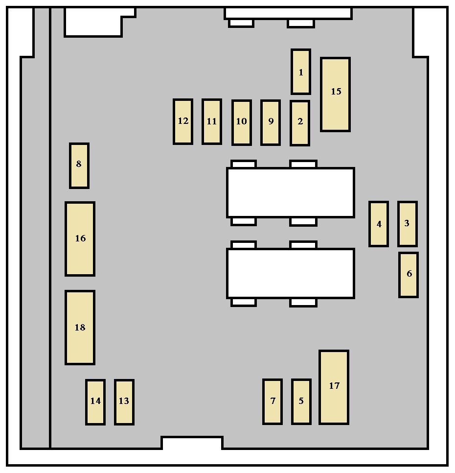
| Fuse | Ampere rating [A] | Functions |
| 1* | 50 | Fan unit |
| 2* | 30 | ESP/ABS pump motor |
| 3* | 30 | ESP/ABS solenoid valves |
| 4* | 70 | Built-in Systems Interface supply |
| 5* | 70 | Built-in Systems Interface supply |
| 6* | — | Not used |
| 7* | 30 | Ignition switch, power |
| 8* | 70 | Power steering electro-pump unit |
| Fuse | Ampere rating [A] | Functions |
| 1 | 10 | Automatic gearbox reversing lights switch – Automatic gearbox starting inhibitor relay control – Manual gearbox reversing lights switch – Vehicle speed sensor – Water in diesel sensor |
| 2 | 15 | Canister solenoid valve – Fuel pump |
| 3 | 10 | Power steering control unit – ABS or ESP control unit |
| 4 | 10 | Injection control unit – Fan unit relay control – Additional heating relay control – Automatic gearbox control unit – Automatic gearbox sequential control – Automatic gearbox shiftlock relay |
| 5 | 15 | Particulate emission filter control unit |
| 6 | 15 | Front fog lamps |
| 7 | — | Not used |
| 8 | 20 | Fan unit relay control – Engine control unit supply – Injection pump (Diesel) |
| 9 | 15 | Left dipped beam |
| 10 | 15 | Right dipped beam |
| 11 | 10 | Right main beam |
| 12 | 10 | Left main beam |
| 13 | 15 | Horn |
| 14 | 10 | Front and rear headlamp wash pump |
| 15 | 30 | Oxygen sensors – Exhaust gas recirculation solenoid valve – Ignition coil – Diesel high pressure regulator – Injectors supply (petrol) – Pre-heat unit – Air flow sensor (Diesel) – Engine control unit supply (Diesel) – Injection pump (Diesel) – Diesel heater |
| 16 | 30 | Petrol engine air pump with automatic gearbox |
| 17 | 30 | Low/high speed front wiper |
| 18 | 40 | Air conditioning blower |
WARNING: Terminal and harness assignments for individual connectors will vary depending on vehicle equipment level, model, and market.