Mercury Villager (1999 – 2002) – fuse box diagram
Year of production: 1999, 2000, 2001, 2002
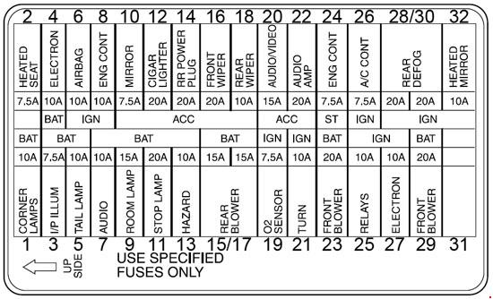
Passenger Compartment Fuse Box
Mercury Villager – fuse box diagram – passenger compartment
№ Fuse A Description
1
Corner Lamps
10
Front Exterior Lamps
2
Heated Seat
7.5
Heated Seats
3
I/P Ilium
7.5
Interior Panel Illumination Lamps
4
Electron
10
Transaxle Control Module (TCM), Electronic Automatic Temperature Control (EATC) Module, Instrument Cluster, Rear Wiper Motor Assembly
5
Tail Lamp
10
Rear Exterior Lamps
6
Air Bag
10
Airbag Diagnostic Monitor
7
Audio
10
Radio, Rear Radio Control, CD Changer
8
Eng Cont
10
Powertrain Control Module, Oxygen Sensors
9
Room Lamp
15
Interior Lamps
10
Mirror
7.5
Smart Entry Control (SEC), Power Mirror Switch
11
Stop Lamp
20
Brake Pedal Position (BPP) Switch, Trailer Tow Control Unit
12
Cigar Lighter
20
Cigar Lighter
13
Hazard
10
Hazard Warning Flasher Switch, Anti-Theft Indicator
14
RR Pwr Plug
20
Rear Powerpoint
15
Rear Blower
15
Rear Blower Motor Relay, Rear Blower Motor
16
Wiper
20
Front Wiper/Washer Assembly
17
Rear Blower
15
Rear Blower Motor Relay, Rear Blower Motor
18
Rear Wiper
10
Rear Wiper/Washer Assembly
19
02 Sensor
7.5
Oxygen Sensor
20
Audio
7.5
’99-’00: Radio
Audio/Video
15
’01-’02: Radio/Video System
21
Turn
10
Hazard Warning Flasher Switch
22
Audio Amp
20
Subwoofer Amplifier
23
Front Blower
20
Front Blower Motor, Front Blower Motor/Speed Controller
24
Eng Cont
7.5
Powertrain Control Module, Lighting Control Module
25
Relays
10
Speed Control, Instrument Cluster, Rear Blower Motor, Data Link Connector #2, Cooling Fans
26
A/C Cont
7.5
Electronic Automatic Temperature Control (EATC) Module, A/C Relay, Front Climate Control Panel
27
Electron
10
Transmission Control, Lighting Control Module, ABS Control Module, Smart Entry Control (SEC)/Timer Module
28
Rear Defog
20
Rear Window Defrost
29
Front Blower
20
Front Blower Motor, Front Blower |Motor/Speed Controller
30
Rear Defog
20
Rear Window Defrost
31
—
—
Not Used
32
Heated Mirror
10
Rear Window Defrost Switch, Power/Heated Mirrors
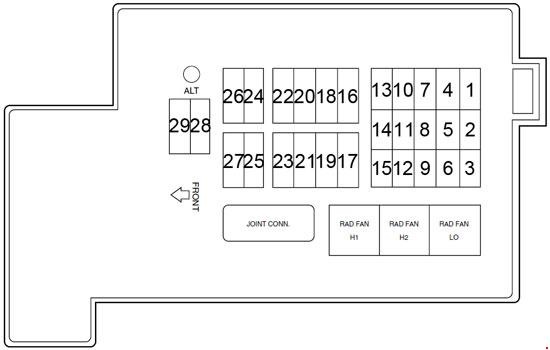
Engine compartment main fuse panel
Mercury Villager – fuse box diagram – engine compartment
№ Fuse A Description
1
FOG LAMP
7.5
’01-’02: Fog Lamps
2
FUEL PUMP
15
Fuel Pump Relay
3
INJ
10
Powertrain Control Module (PCM), Injectors
4
SEC
7.5
Anti-Theft Relay, Smart Entry Control (SEC)/Timer Module
5
RAD
7.5
Radiator Fan Sensing
6
ECCS
10
Data Link Connector (DLC) #1, PCM Power Relay
7
—
—
Not Used
8
—
—
Not Used
9
ALT
10
Generator
10
ABS
20
ABS Control Module
11
—
—
Not Used
12
H/L RH
15
Lighting Control Module
13
HORN
15
Horn Relay
14
—
—
Not Used
15
H/L LH
15
Lighting Control Module
16
—
—
Not Used
17
—
—
Not Used
18
ABS
40
ABS Control Module
19
—
—
Not Used
20
PWR WND
30
Power Window Relay, Smart Entry Control (SEC)/Timer Module, Power Seats
21
RAD FAN LO
20
Low Speed Fan Control Relay
22
—
—
Not Used
23
IGN SW
30
Ignition Switch
24
—
—
Not Used
25
RAD FAN
75
High Speed Fan Control Relay
26
FR BLW
65
Front Blower Motor Relays
27
RR DEF
45
Rear Window Defroster Relay
28
ALT
140
Accessory Relay, Ignition Relay, Tail Lamp Relay, Fuse Junction Panel
29
MAIN
100
Generator
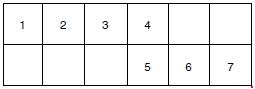
Additional Relay Box
Mercury Villager – fuse box diagram – additional relay box
№ Relay
1
Start Inhibit
2
Fuel Pump
3
Bulb Check
4
’99-’00: Speed Control Hold
’01-’02: Fog Lamp
5
Anti-theft
6
Horn
7
A/C
WARNING: Terminal and harness assignments for individual connectors will vary depending on vehicle equipment level, model, and market