Mercury Mystique (1995 – 2000) – fuse box diagram
Year of production: 1995, 1996, 1997, 1998, 1999, 2000
Passenger Compartment Fuse Box
Mercury Mystique – fuse box diagram – passenger compartment
No. A Fused component
19
7.5
’95-’97: Heated rear view mirrors
20
10
Circuit breaker:
21
40
Power windows
22
7.5
’95-’99: ABS module
23
15
Backup lamps
24
15
Brake lamps
25
20
Door locks
26
7.5
Main light
27
15
Cigar lighter
28
30
Electric seats
29
30
Rear window defrost
30
7.5
Engine management system
31
7.5
Instrument panel illumination
32
7.5
Radio
33
7.5
Parking lamps – driver’s side
34
7.5
Interior lighting/electric mirror adjustment
35
7.5
Parking lamps – passenger’s side
36
10
’95-’98: Air bag
37
30
Heater blower motor
38
—
Not used
Relay
R12
Interior lighting
R13
Rear window defrost
R14
Heater blower motor
R15
Wiper motor
R16
Ignition
Diode
D2
Reverse voltage protection
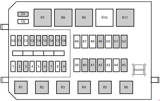
Engine Compartment Fuse Box (’99-’00)
Mercury Mystique – fuse box diagram – engine compartment
No. A Fused component
1
—
Not used
2
7.5
Alternator
3
20
Foglamps
4
—
Not used
5
—
Not used
6
3
EEC ignition module (memory)
7
20
Horn and hazard flasher warning system
8
—
Not used
9
15
Fuel pump
10
—
Not used
11
20
Ignition, Electronic Engine Control
12
—
Not used
13
20
HEGO sensor
14
7.5
ABS module
15
7.5
Low beam headlamp (passenger’s side)
16
7.5
Low beam headlamp (driver’s side)
17
7.5
High beam headlamp (passenger’s side)
18
7.5
High beam headlamp (driver’s side)
39
—
Not used
40
20
Ignition, light switch, central junction box
41
20
EEC relay
42
40
Central junction box (fuse 37 to blower relay)
43
—
Not used
44
—
Not used
45
60
Ignition
46
—
Not used
47
—
Not used
48
—
Not used
49
60
Engine cooling
50
—
Not used
51
60
ABS
52
60
Central junction box (central timer module, rear window defrost relay, fuses 24, 25, 27, 28, 34)
Relay
R1
Fuel pump
R2
EEC module
R3
Air conditioning
R4
Low beam
R5
High beam
R6
Horn
R7
Starter solenoid
R8
Engine cooling fan (high speed)
R9
Engine cooling fan
R10
Not used
R11
Daytime running lights
Diode
D1
Reverse voltage protection
D2
Not used
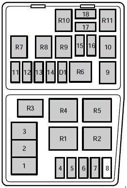
Engine Compartment Fuse Box (’95-’98)
Mercury Mystique – fuse box diagram – engine compartment
No. A Fused component
1
80
Main power supply to vehicle electrical system
2
60
Engine cooling fan
3
60
ABS braking system, heater blower (’98)
4
20
Ignition, Daytime running lights
5
15
Foglamp
6
—
Not used
7
20
’98: ABS system
30
’95-’97: ABS system
8
30
’95-’97: Air pump
9
20
Electronic Engine Control (EEC)
10
20
Ignition switch
11
3
EEC ignition module (memory)
12
15
Horn and hazard flasher warning system
13
20
’98: HEGO sensor
15
’95-’97: HEGO sensor
14
15
Electrically operated fuel pump
15
10
Low beam headlamp – (passengers side)
16
10
Low beam headlamp – (driver’s side)
17
10
High beam headlamp – (passengers side)
18
10
High beam headlamp – (driver’s side)
Relay
R1
Daytime running lights
R2
Radiator fan relay (high speed)
R3
Air conditioning
R4
Air conditioning clutch relay
R5
Radiator fan relay (low speed)
R6
Starter solenoid
R7
Horn
R8
Fuel pump
R9
Low beam headlamps
R10
High beam headlamps
R11
PCM module
Diode
D1
Reverse voltage protection
Auxiliary relays (outside of fuse boxes (’99-’00))
No. Circuits switched Location
R18
“One touch” switch (drivers window)
Driver’s door
R22
Foglamps
Wire shield on instrument panel
R23
Turn signals
Steering column
R24
Panic alarm – driver’s side
Door lock module bracket
R25
Panic alarm – right-hand side
Door lock module bracket
R32
Hego heater control (’00)
Near PCM-Module
WARNING: Terminal and harness assignments for individual connectors will vary depending on vehicle equipment level, model, and market.