
Mercedes-Benz E-Class w211 (2002 – 2009) – fuse box diagram
Year of production: 2002, 2003, 2004, 2005, 2006, 2007, 2008, 2009
Fuse box in the trunk
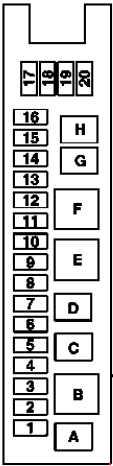
| No. | Fused function | A |
| 1 | Front passenger partially-electric seat adjustment switch Driver-side front seat adjustment control unit, with memory |
30 |
| 2 | Driver partially-electric seat adjustment switch Passenger-side front seat adjustment control unit with memory |
30 |
| 3 | Tire pressure monitor control unit PARKTRONIC control unit TV combination tuner (analog/digital) Navigation processor |
7,5 |
| 4 | Except engine 113.990 (E55 AMG), 156.983 (E 63 AMG):Fuel pump | 15 |
| 201) | ||
| Engine 113.990 (E55 AMG): Charge air cooler circulation pump | 15 | |
| 5 | — | — |
| 6 | Audio gateway control unit | 40 |
| 7 | Rear-end door control unit | 15 |
| 8 | Left antenna amplifier module ATA [EDW] inclination sensor Alarm horn |
7,5 |
| 9 | Overhead control panel control unit | 25 |
| 10 | Heated rear window | 40 |
| 11 | Rear-end door control unit | 20 |
| 12 | Cargo area connector box | 15 |
| 13 | Interior socket | 15 |
| 14 | — | — |
| 15 | Fuel filler flap CL [ZV] motor | 10 |
| 16 | Seat heating and seat ventilation control unit | 20 |
| 17 | Trailer connection unit control unit | 20 |
| 18 | Trailer connection unit control unit | 20 |
| 19 | Multicontour seat pneumatic pump | 20 |
| 20 | Rear window roller blind relay | 7,5 |
| Relay | ||
| A | Fuel pump relay (except engine 113.990 (E55 AMG), 156.983 (E 63 AMG)) Engine 113.990 (E55 AMG): Charge air cooler circulation pump relay |
|
| B | Relay 2, terminal 15R | |
| C | Spare relay 2 | |
| D | Rear wiper relay | |
| E | Heated rear window relay | |
| F | Relay 1, terminal 15R | |
| G | Fuel filler cap polarity reverser relay 1 | |
| H | Fuel filler cap polarity reverser relay 2 | |
| 1) as of 2007 | ||
The Instrument Panel Fuse Panel
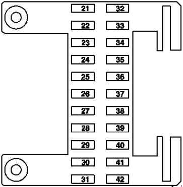
| No. | Fused function | A |
| Feed-in:Rear prefuse box | 150 | |
| 21 | Right rear door control unit | 25 |
| 301) | ||
| 22 | Right front door control unit | 25 |
| 301) | ||
| 23 | Front passenger front seat adjustment control unit with memory | 30 |
| 24 | Circuit 30 connector sleeve, Keyless Go | 25 |
| 25 | Stationary heater unit | 25 |
| In addition fused via polyswitch fuse for stationary heater: Stationary heater radio remote control receiver | 5 | |
| 26 | CD changer | 7,5 |
| 27 | Terminal 15 relay (as of 2007) | 5 |
| 28 | Radio COMAND operating, display and control unit |
5 |
| Radio control panel and navigation unit COMAND operating, display and control unit |
15 | |
| 29 | Steering column module EIS [EZS] control unit |
7,5 |
| up to 2006: DC/DC converter control unit | 15 | |
| 30 | Data link connector | 7,5 |
| 31 | Upper control panel control unit Cutoff relay for interruptible loads (2006-2007) |
5 |
| up to 2006: Driver-side SAM control unit with fuse and relay module | 7,5 | |
| 32 | Left rear door control unit | 30 |
| 33 | Left front door control unit | 30 |
| 34 | Driver-side front seat adjustment control unit, with memory | 30 |
| 35 | WSS (Weight Sensing System) control unit (as of 2007; USA) | 5 |
| 36 | Heated seats and seat ventilation control unit | 25 |
| 37 | AIRmatic with ADS control unit | 15 |
| 38 | NECK-PRO head restraints relay | 7,5 |
| 39 | Lower control panel control unit | 5 |
| 40 | Heated seats and seat ventilation control unit | 10 |
| up to 2006: Upper control panel control unit | 5 | |
| 41 | Central gateway control unit | 5 |
| 42 | Cutoff relay for interruptible loads (up to 2006) ME-SFI [ME] control unit Valid for engine 629, 642, 646 EVO:Terminal 87 relay, engine Driver-side SAM control unit with fuse and relay module (engine 271, 272, 628, 629, 642, 646, 647, 648) CNG control unit (engine 271) |
7,5 |
| 1) as of 2007 | ||
Fuse box in the engine compartment
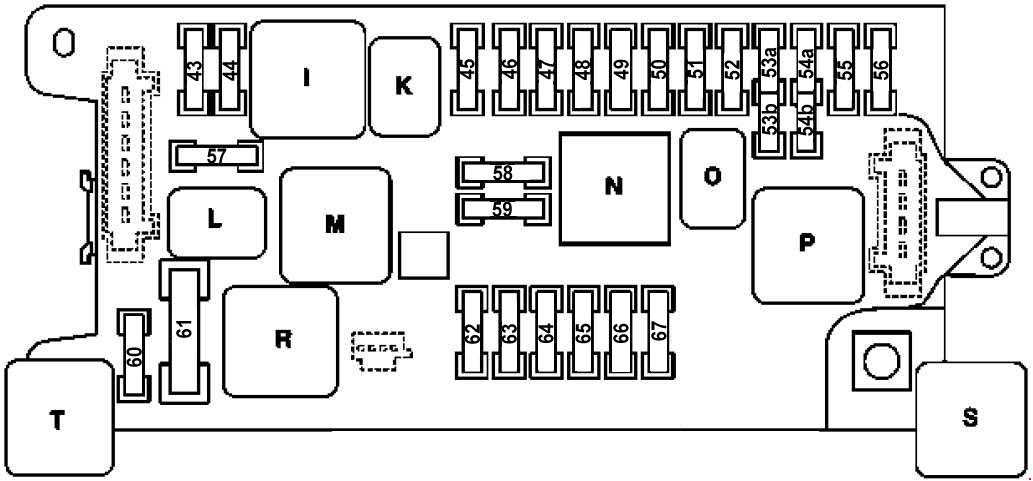
| No. | Fused function | A |
| 43 | Valid for engine 112, 113, 156, 271, 272, 273:ME-SFI [ME] control unit Valid for engine 271, 272, 273:ME control unit Valid for engines 628, 629, 642, 646, 647, 648: CDI control unit Driver-side SAM control unit with fuse and relay module Rear SAM control unit with fuse and relay module Valid for engine 629, 642, 646, 647, 648: CDI control unit Rear SAM control unit with fuse and relay module |
15 |
| 44 | Valid for engine 646, 647, 648:CDI control unit Valid for engine 271, 272, 273:ME-SFI [ME] control unit Valid for engine 271 (Bivalent natural gas drive): Cyl. 1 gas injection valve Cyl. 2 gas injection valve Cyl. 3 gas injection valve Cyl. 4 gas injection valve |
15 |
| 45 | AIRmatic with ADS control unit Electronic selector lever module control unit (Automatic five-speed transmission (NAG)) Rear axle level control system control unit Gear recognition switch (Sequentronic automated manual transmission (SEQ)) |
7,5 |
| 46 | ETC [EGS] control unit (Automatic 5-speed transmission (NAG)) VGS electric control unit (automatic 7-speed transmission) Automated manual transmission control unit (Sequentronic automated manual transmission (SEQ)) |
7,5 |
| 47 | ESP, SPS [PML] and BAS control unit | 5 |
| 48 | Restraint systems control unit Left front reversible emergency tensioning retractor (as of 2007) Right front reversible emergency tensioning retractor (as of 2007) |
7,5 |
| 49 | Restraint systems control unit Front passenger seat occupied and child seat recognition sensor NECK-PRO head restraints relay |
7,5 |
| 50 | Portable CTEL separation point VICS power supply separation point Emergency call system control unit |
5 |
| 51 | Spare | 5 |
| 52 | Exterior lamp switch Instrument cluster Glove compartment illumination with switch AAC with integrated control additional fan motor (as of 2007) Bi-xenon headlamp unit:Headlamp range adjustment control unit |
7,5 |
| 53a | Spare | 15 |
| 53b | Fanfare horn relay | 15 |
| 54a | Illuminated cigar lighter | 15 |
| 54b | Illuminated cigar lighter | 15 |
| 55 | Telephone handset (up to 2007) Bluetooth module connector (up to 2007) Portable CTEL separation point Emergency call system control unit (as of 2007) |
7,5 |
| 56 | Wiper motor | 40 |
| 57 | Valid for engine 628, 646, 647, 648:CDI control unit Valid for engine 271, 272, 273: ME-SFI [ME] control unit Purge control valve PremAir Sensor USA version:Activated charcoal canister shut-off valve |
25 |
| 58 | Valid for engine 112, 113, 156: Cylinder 1 ignition coil Cylinder 2 ignition coil Cylinder 3 ignition coil Cylinder 4 ignition coil Cylinder 5 ignition coil Cylinder 6 ignition coil Cylinder 7 ignition coil Cylinder 8 ignition coil |
15 |
| 59 | Starter relay | 15 |
| 201) | ||
| 60 | Oil cooler fan (E55 AMG, E63 AMG) | 10 |
| 61 | Electric air pump | 40 |
| 62 | SEQ pump control relay (Sequentronic automated manual transmission (SEQ)) | 30 |
| 63 | Automated manual transmission control unit (Sequentronic automated manual transmission (SEQ)) Valid for engines 112, 113: Circuit 87 relay, engine ME-SFI [ME] control unit |
15 |
| 64 | Exterior lamp switch Instrument cluster AAC [KLA] control and operating unit Comfort AAC [KLA] control and operating unit Steering column module (up to 2007) |
7,5 |
| 65 | IS [EZS] control unit Electric steering lock control unit |
20 |
| 66 | Right front lamp unit Left front lamp unit HRA [LWR] selector wheel (as of 2007) Bi-xenon headlamp unit:HRA power module |
7,5 |
| 67 | Stop light switch | 5 |
| Relay | ||
| I | Terminal 87 relay, engine | |
| K | Terminal 87 relay, chassis | |
| L | Starter relay | |
| M | SEQ pump control relay | |
| N | Terminal 15 relay | |
| O | Fanfare horn relay | |
| P | Terminal 15R relay | |
| R | Air pump relay (except engine 113.990 (E55 AMG), 156.983 (E63 AMG)) Oil cooler fan (only engine 113.990 (E55 AMG), 156.983 (E63 AMG)) |
|
| S | Airmatic relay | |
| 1) as of 2007 | ||
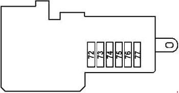
Front prefuse box
Front
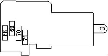
Rear
| No. | Fused function | A |
| Feed-in:Battery (G1) | ||
| 68 | Valid for engine 629, 642, 646, 647, 648:Heater booster | 200 |
| 69 | Valid for engine 629, 642, 646 EVO:Glow time output stage | 150 |
| 70 | External start terminal point | — |
| 71 | Valid for engine 112, 113, 156, 271, 272, 273, 629, 642, 646, 647, 648:AAC with integrated control additional fan motor | 150 |
| Valid for engine 629, 642, 646 EVO:Engine and AC electric suction fan with integrated control | 100 | |
| 72 | Traction system hydraulic unit | 50 |
| 73 | Traction system hydraulic unit as of 2007: ESP control unit |
50 |
| 74 | AIRmatic relay | 40 |
| 75 | Right SAM control unit | 40 |
| 76 | Right front reversible emergency tensioning retractor Engine 113.990 (E 55 AMG): Air injection relay |
40 |
| 77 | Blower motor Heating systems recirculation unit Solar generator control unit |
40 |
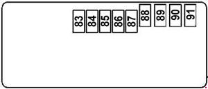
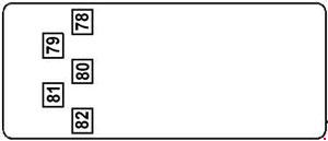
Rear prefuse box
Front
Rear
| No. | Fused function | A |
| Feed-in:Battery | ||
| 78 | Driver-side SAM control unit with fuse and relay module | 200 |
| 79 | Rear SAM control unit with fuse and relay module | 200 |
| 80 | Driver-side SAM control unit with fuse and relay module | 150 |
| 81 | Interior fuse box | 150 |
| 82 | Valid for engine 113.990 (E55 AMG), 156.983 (E63 AMG):Fused via terminal 30 connector sleeve: Fuse F82A and F82B | 150 |
| F82A | Fuse for left fuel pump control unit (156.983 (E63 AMG)) Fuse for right fuel pump control unit (156.983 (E63 AMG)) |
40 |
| Fuel pump relay (113.990 (E55 AMG), 156.983 (E63 AMG)) | 30 | |
| F82B | Air injection relay fuse | 40 |
| 83 | Taxi version:Special vehicle multifunction control unit (SVMCU [MSS]) | 30 |
| 84 | Battery sensor | 5 |
| 85 | Telephone interface Universal Portable CTEL Interface (UPCI [UHI]) control unit Hands-free system control unit Voice control system control unit |
5 |
| 86 | Interior socket (5A – up to 2003; 30A – 2004-2006; 5A – as of 2007) | |
| USA version:SDAR control unit | 5 | |
| Valid for government vehicles:Special vehicle multifunction control unit (SVMCU [MSS]) Taxi version:Special vehicle multifunction control unit (SVMCU [MSS]) |
30 | |
| 87 | Pneumatic pump for dynamic seat control | 30 |
| 88 | TLC [HDS] control unit Rear-end door closing control unit |
30 |
| 89 | Loading floor control unit | 40 |
| 90 | Left front reversible emergency tensioning retractor Special vehicle multifunction control unit (SVMCU [MSS]) |
40 |
| Up to 02/03 for engine 113.990 (E55 AMG): Fuel pump relay | 30 | |
| 91 | Special vehicle multifunction control unit (SVMCU [MSS]) | 40 |
WARNING: Terminal and harness assignments for individual connectors will vary depending on vehicle equipment level, model, and market.