
Land Rover Discover (2004 – 2009) – fuse box diagram
Year of production: 2004, 2005, 2006, 2007, 2008, 2009
Fuse box locations
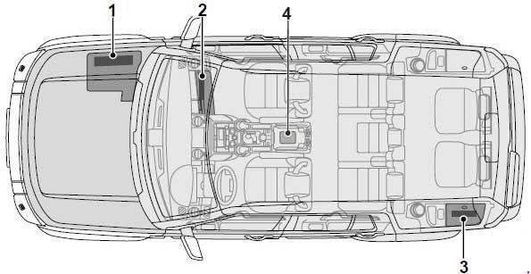
- Engine compartment fuse box.
- Passenger compartment fuse box.
- Tow hitch fuse box.
- 6 way satellite ATO fuse box (Armoured)
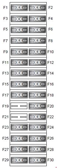
Engine compartment fuse box

| No. |
A |
Circuits protected |
| 1 | 25 | Fuel pump |
| 2 | – | – |
| 3 | 5 | Air suspension ECU |
| 4 | 25 | Diesel – diesel EMS (ECU & fuel pump relay control) |
| 5 | 10 | Petrol – petrol EMS (purge valve, EGR, inlet manifold tune valve), E-Box fan |
| 6 | 15 | Petrol EMS (ignition coils) |
| 6 | 15 | from 2007: Diesel EMS (Sensors and glow plug relay control) |
| 7 | 25 | Front seat heater |
| 8 | 25 | Rear seat heater |
| 9 | 15 | up to 2005: Active roll control |
| 10 | 15 | Petrol – petrol EMS (throttle motor, MAF), cool fan |
| 10 | 15 | Diesel – cooling fan |
| 11 | 15 | Petrol – petrol EMS (rear oxygen sensors) |
| 12 | 10 | Heated washer jets |
| 13 | 10 | Petrol – petrol EMS (ECU, VVTs and fuel pump relay control) |
| 13 | 10 | Diesel EMS (PCV, VCV) |
| 14 | 20 | Petrol – petrol EMS (front oxygen sensors) |
| 15 | 30 | Heated front screen |
| 16 | 10 | Heated door mirrors |
| 17 | 15 | Petrol – petrol EMS (injectors) |
| 17 | 15 | Diesel EMS (MAF, EGR), E-Box fan |
| 18 | 30 | Heated front screen |
| 19 | – | – |
| 20 | 5 | Alternator |
| 21 | – | – |
| 22 | 30 | Rear blower |
| 23 | 25 | Dynamic Stability Control system |
| 24 | 20 | Petrol – brake boost pump |
| 25 | 10 | Lighting switch |
| 26 | 20 | Air suspension ECU |
| 27 | 5 | Engine Control Module (ECM) |
| 28 | 20 | Diesel – auxiliary heater |
| 29 | 30 | Front wipers |
| 30 | 10 | Auto transmission ECU |
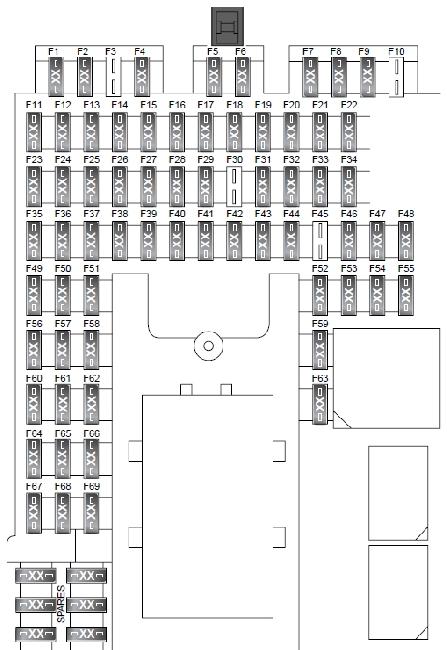
Passenger compartment fuse box

| No. |
A |
Circuits protected |
| 1 | 10 | Interior lamps – glovebox lamp, vanity mirror lamp, map lamps, switchable roof lamps. Electric seats (non memory). |
| 2 | 10 | Right-hand side lamps |
| 3 | 10 | up to 2005: Theatre lamps |
| 4 | 10 | Left-hand side lamps |
| 5 | 10 | Reverse lamps |
| 6 | 10 | Trailer reverse lamp |
| 7 | 25 | Driver’s window |
| 8 | 30 | Trailer pick-up (battery feed) |
| 9 | 5 | up to 2006: SRS from 2007: Airbags |
| 10 | – | – |
| 11 | 15 101) |
Washer pump |
| 12 | 15 | Horn |
| 13 | 25 | Heated rear window |
| 14 | 10 | Trailer side lamp |
| 15 | 15 | Brake lamps, Brake switch |
| 16 | 10 | Powerfold mirror |
| 17 | 20 | Rear right-hand window |
| 18 | 5 | Rain sensor, ambient light sensor (auto lamps) |
| 19 | 15 | Auxiliary power socket – 2nd row seats |
| 20 | 15 | Sunroof |
| 21 | 25 | Passenger window |
| 22 | 10 | Trailer pick-up (ignition feed) |
| 23 | – | – |
| 24 | 5 | Transfer box – centre differential, Terrain Response |
| 25 | 5 | Engine Control Module (ECM) |
| 26 | 5 | Battery back-up sounder |
| 27 | 10 | Adaptive front lighting / Headlamp levelling |
| 28 | 5 | Fuse box engine compartment – ignition |
| 29 | 30 | Passenger electric sea |
| 30 | – | – |
| 31 | 20 | Rear left-hand window |
| 32 | 15 | Rear fog lamps |
| 33 | 5 | Mirror adjust, Automatic transmission selector, passenger electric seat (up to 2005). |
| 34 | 15 | Auxiliary power socket – front seats |
| 35 | 5 | Air suspension ECU |
| 36 | 5 | Park Distance Control, Tyre pressure monitoring system |
| 37 | 5 | Dynamic Stability Control |
| 38 | 15 | Front fog lamps |
| 39 | 5 | Instrument pack |
| 40 | 5 | Key-in sense |
| 41 | 5 | Electric Parking Brake (EPB) |
| 42 | 30 | Audio amplifier |
| 43 | 10 | Radio frequency receiver, Tyre Pressure Monitoring system |
| 44 | 5 | Automatic transmission selector |
| 45 | – | – |
| 46 | 30 | Drivers electric seat |
| 47 | 15 | Auxiliary power socket – 3rd row seats |
| 48 | 15 | Rear wiper |
| 49 | 30 | Central door locking |
| 50 | 10 | Electric fuel flap actuator |
| 51 | 10 | Climate control ECU |
| 52 | 5 | Telephone, traffic message centre |
| 53 | 15 | Multi-media module, audio unit, DVD player |
| 54 | 5 | Electric seat – memory, lumbar pump |
| 55 | 15 | Cigar lighter |
| 56 | 10 | Adaptive front lighting (left-hand unit) |
| 57 | 10 | Rear seat entertainment module |
| 58 | 10 | Telephone, touch screen display, multi-media module, TV tuner |
| 59 | 10 | Cubby box cooler |
| 60 | 5 | Engine control module (ECM) |
| 61 | 10 | Adaptive front lighting (right-hand unit) |
| 62 | 5 | Low beam, auto lamps |
| 63 | 10 | Diagnostic socket |
| 64 | 5 | Automatic transmission ECU |
| 65 | – | – |
| 66 | 5 | HDC switch, Brake switch, Steering angle sensor, DSC switch |
| 67 | 5 | Auto lamps |
| 68 | 5 | Instrument pack |
| 69 | 5 | Automatic dimming interior mirrors Electrochromatic mirror, Homelink (up to 2005). |
| 1) 2005 | ||
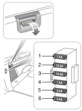
Tow hitch fuse box
| No. |
A |
Circuits protected |
| 1 | 7.5 | Brake lamp |
| 2 | 15 | Ignition feed |
| 3 | 15 | Battery feed |
| 4 | 7.5 | Rear fog lamps |
| 5 | 5 | Right-hand tail lamp |
| 6 | 5 | Number plate and left-hand tail lamp |
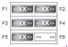
Satellite fuse box (Armoured)
The six way satellite ATO fuse box is mounted in the base of the centre console cubby box.
To access the fuses, remove the CD holder and cubby box floor. The fuse box has a removable transparent cover.
| No. |
A |
Circuits protected |
| 1 | 5 | Intercom |
| 2 | 20 | Siren |
| 3 | 5 | Covert lamps |
| 4 | 10 | Beacon |
| 5 | 3 | Battery status monitor |
| 6 | 30 | Additional equipment |
Any electrical equipment other than Land Rover approved accessories must be connected to the spare terminal (F6) only. The additional electrical equipment should be protected with an appropriate fuse not exceeding 30 amps.
WARNING: Terminal and harness assignments for individual connectors will vary depending on vehicle equipment level, model, and market.