
Kubota Tractor M96SDTM – fuse box diagram
Year of production:
Fuse box
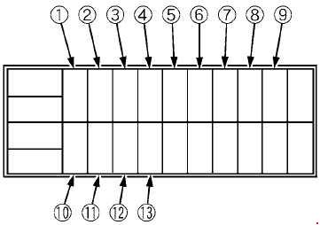
| Number | Ampere ratting [A] | Protected circuit |
| 1 | 15 | Flasher (Hazard) |
| 2 | 15 | Head Light |
| 3 | 10 | Tail Lamp, Horn |
| 4 | 5 | Engine, PTO. Alternator |
| 5 | 10 | T/M Control |
| 6 | 5 | Meter Panel, OPC, Buzzer |
| 7 | 10 | Turn Signal |
| 8 | 15 | AUX Power |
| 9 | 5 | Relay |
| 10 | 15 | Work Light RH (Front, F/S) |
| 11 | 15 | Work Light LH (Rear) |
| 12 | 5 | Meter Backup |
| 13 | 10 | Brake Lamp |
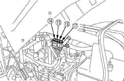
| Number | Ampere ratting [A] | Protected circuit |
| 14 | 100 | Charge |
| 15 | 120 | Heater |
| 16 | 30 | Main Key Switch |
| 17 | 50 | Head Light, Work Light |
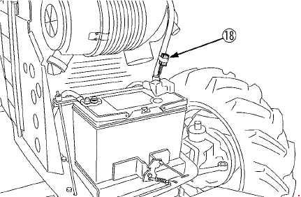
| Number | Ampere ratting [A] | Protected circuit |
| 18 | 10 | CRS Power [M108S] |
WARNING: Terminal and harness assignments for individual connectors will vary depending on vehicle equipment level, model, and market.