
Infiniti M35 (2006 – 2010) – fuse box diagram
Year of production: 2006, 2007, 2008, 2009, 2010
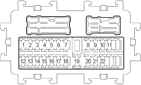
Passenger Compartment Fuse Box
| No. |
A |
Circuit Protected |
| 1 | 15 | Body Control Module (BCM), Engine Control Module (ECM), Fuel Injectors, Power Window, Door Lock System, Turn Signal and Hazard Warning Lamps, Interior Room Lamps, Sunroof |
| 2 | – | – |
| 3 | – | – |
| 4 | – | – |
| 5 | 15 | Power Socket (Floor Console Inside), Power Socket (Floor Console Rear) |
| 6 | 10 | Multi-Function Switch, Unified Meter and A/C Amplifier, Rear Control Switch, AV Control Unit, Satellite Radio Tuner, Tel Adapter Unit, Front Display Unit, CD Changer, iPod Adapter, Camera Control Unit, BOSE Amplifier, DVD Player, Video Distribution, Rear Display Unit, Body Control Module (BCM), Intelligent Key Unit, Combination Meter, Interior Room Lamps |
| 7 | 15 | Cigarette Lighter Socket |
| 8 | 10 | Heated Mirror |
| 9 | – | – |
| 10 | 15 | Blower Motor |
| 11 | 15 | Blower Motor |
| 12 | 10 | Intelligent Cruise Control (ICC) Brake Switch, Lane Departure Warning (LDW) Switch, Lane Camera Unit, Lane Departure Warning Buzzer, Unified Meter and A/C Amplifier, Data Link Connector, Shift Lock Relay, A/C Compressor, AV Control Unit, Tel Adapter Unit, Intelligent Key Unit, Automatic Speed Control Device (ASCD) Brake Switch, Cooling Fan Relay, Rear Sunshade Unit, Rear Sunshade Cancel Relay, Auto Anti-Dazzling Inside Mirror, Rear Window Defogger Relay, Adaptive Front Lighting System (AFS) Switch, AFS Control Unit, Aiming Motors, Low Tire Pressure Warning Control Unit, Front Wiper Relay |
| 13 | 10 | Air Bag Diagnosis Sensor Unit, Occupant Classification System Control Unit |
| 14 | 10 | Combination Meter, Back-Up Lamp Relay, AV Control Unit, Camera Control Unit |
| 15 | 10 | Pre-Crash Seat Belt Control Unit |
| 16 | – | – |
| 17 | 15 | BOSE Amplifier |
| 18 | 15 | BOSE Amplifier |
| 19 | 10 | Unified Meter and A/C Amplifier, Data Link Connector, Auto Anti-Dazzling Inside Mirror, Homelink Universal Transceiver, Compass, Rain Sensor |
| 20 | 10 | Stop Lamp Switch, Intelligent Cruise Control (ICC) Brake Hold Relay, Intelligent Key Unit |
| 21 | 10 | Combination Meter, Body Control Module (BCM), Power Window, Door Lock System, Automatic Drive Positioner Control Unit, Power Seat, Turn Signal and Hazard Warning Lamps, Interior Room Lamps, Sunroof |
| 22 | 10 | Key Slot, Push-Button Ignition Switch, Intelligent Key Unit, Intelligent Key Warning Buzzer, Power Distribution Unit (PDU), |
| No. |
Relay |
| R1 | Blower |
| R2 | Accessory |
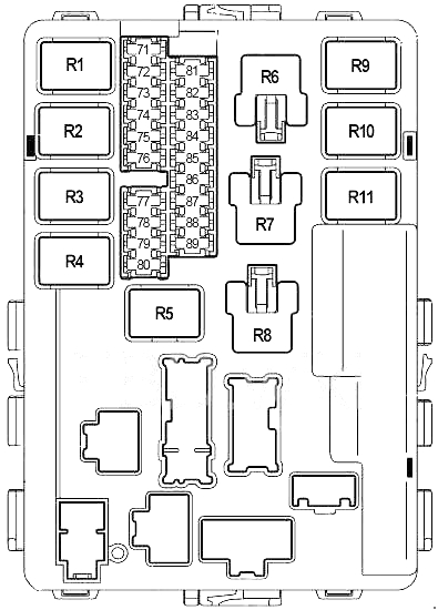
Engine Compartment Fuse Box No.1
| No. |
A |
Circuit Protected |
| 71 | 15 | IPDM CPU, Tail Lamp Relay (Front/Rear Combination Lamps, License Plate Lamps, Illumination, Illumination Switchs, Rear Sunshade) |
| 72 | 10 | Right Headlamp (High Beam) |
| 73 | 30 | Front Wiper Relays |
| 74 | 10 | Left Headlamp (High Beam) |
| 75 | 20 | Rear Window Defogger Relay |
| 76 | 15 | Right Headlamp (Low Beam) |
| 77 | 20 | Engine Control Module (ECM) Relay (Engine Control Module, Ignition Coils, Condenser, Intake Valve Timing Control Solenoid Valve, Exhaust Valve Timing Control Magnet Retarder (VQ35HR), Mass Air Flow Sensor, EVAP Canister Purge Volume Control Solenoind Valve, EVAP Canister Vent Control Valve, Intake Valve Timing Control Position Sensor (VK45DE), Crankshaft Position Sensor (VK45DE), Camshaft Position Sensor (VK45DE), Intake Valve Timing Control Position Sensor (VK45DE), VIAS Control Solenoid Valve (VK45DE)) |
| 78 | 15 | IPDM CPU |
| 79 | 10 | Air Conditioner Relay |
| 80 | 20 | Rear Window Defogger Relay |
| 81 | 15 | Fuel Pump Relay |
| 82 | 10 | Intelligent Cruise Control (ICC) Sensor Integrated Unit, Steering Angle Sensor, ABS/VDC/TCS Control Unit, Yaw Rate/Side G Sensor, Power Steering Control Unit, Rear Active Steer (RAS) Control Unit, All Wheel Drive (AWD) Control Unit |
| 83 | 10 | Transmission Control Module (TCM), Snow Mode Switch |
| 84 | 10 | Front Wiper Motor, Front Washer Pump |
| 85 | 15 | Air Fuel Ratio Sensors, Heated Oxygen Sensors, |
| 86 | 15 | Left Headlamp (Low Beam) |
| 87 | 15 | Throttle Control Motor Relay |
| 88 | 15 | Front Fog Lamp Relay |
| 89 | – | – |
| Relay |
||
| R1 | Engine Control Module | |
| R2 | Headlamp High | |
| R3 | Headlamp Low | |
| R4 | Starter | |
| R5 | Ignition | |
| R6 | – | |
| R7 | – | |
| R8 | Heated Seat | |
| R9 | Throttle Control Motor | |
| R10 | Fuel Pump | |
| R11 | Front Fog Lamp | |
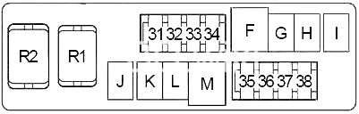
Engine Compartment Fuse Box No. 2
| No. |
A |
Circuit Protected |
| 31 | 20 | Rear Active Steer (RAS) Motor Relay |
| 32 | 10 | Daytime Light Relay |
| 33 | 10 | All Wheel Drive (AWD) Control Unit |
| 34 | 10 | Transmission Control Module (TCM) |
| 35 | 15 | Horn Relay |
| 36 | 10 | Alternator |
| 37 | 15 | Multi-Function Switch, AV Control Unit, Satellite Radio Tuner, Tel Adapter Unit, Front Display Unit, CD Changer, iPod Adapter, Camera Control Unit, DVD Player, Video Distribution, Rear Display Unit, Security Indicator |
| 38 | 15 | Heated Seat Relay |
| F | 50 | Body Control Module (BCM), Power Window, Door Lock System, Power Seat, Turn Signal and Hazard Warning Lamps, Interior Room Lamps, Sunroof, Automatic Drive Positioner Control Unit |
| G | 30 | Pre-Crash Seat Belt Control Unit |
| H | 30 | Ignition, Power Distribution Unit (PDU) |
| I | 50 | Cooling Fan Relay |
| J | 50 | ABS/VDC/TCS Control Unit |
| K | 30 | ABS/VDC/TCS Control Unit |
| L | – | – |
| M | 40 | Starter, Power Distribution Unit (PDU) |
| Relay |
||
| R1 | Horn | |
| R2 | Back-Up Lamp | |
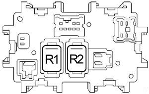
Engine Compartment Fuse Box No.3
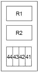
| No. |
A |
Circuit Protected |
| 41 | 15 | Climate Controlled Seat Relay (Passenger Side) |
| 42 | 15 | Climate Controlled Seat Relay (Driver Side) |
| 43 | – | – |
| 44 | – | – |
| Relay |
||
| R1 | Climate Controlled Seat | |
| R2 | Intelligent Cruise Control (ICC) Brake Hold | |
Fusible Link Block
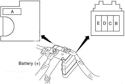
| No. |
A |
Circuit Protected |
| A | 140 | Alternator (VK45DE or AWD), Fuse: “B”, “C” |
| B | 100 | Fuse: “31”, “32”, “33”, “34”, “35”, “36”, “37”, “38”, “F”, “G”, “H”, “I”, “J”, “K”, “M” |
| C | 80 | Headlamp High Relay (Fuse: “72”, “74”), Headlamp Low Relay (Fuse: “76”, “86”), Fuse: “71”, “73”, “75”, “87”, “88” |
| D | 60 | Accessory Relay (Fuse: “5”, “6”, “7”), Blower Relay (Fuse: “10”, “11”), Fuse: “17”, “18”, “19”, “20”, “21”, “22”, “41”, “42” |
| E | 80 | Ignition Relay (Air Conditioner Relay, Front Wiper Relay, Front Wiper High Relay, Fuse: “81”, “82”, “83”, “84”, “85”), Fuse: “77”, “78”, “79”, “80” |
WARNING: Terminal and harness assignments for individual connectors will vary depending on vehicle equipment level, model, and market.