Hyundai Porter (2004 – 2016) – fuse box diagram
Year of production: 2004, 2005, 2006, 2007, 2008, 2009, 2010, 2011, 2012, 2013, 2014, 2015, 2016
Location
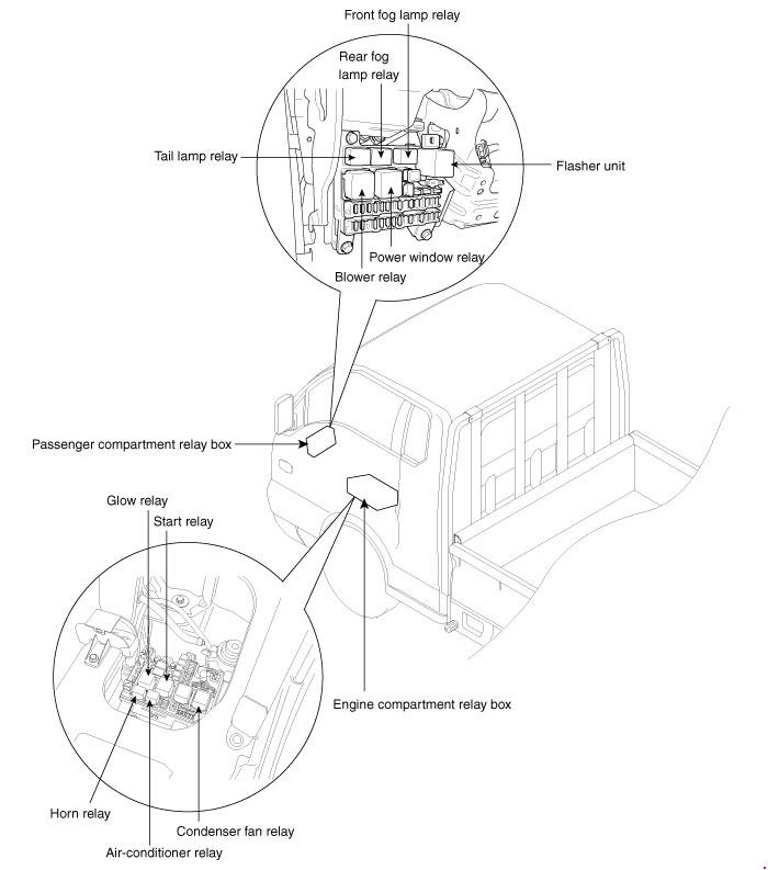
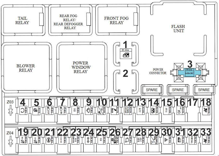
Passenger compartment fuse box
| No. |
A |
Function/component |
| 1 | Power Window Relay | |
| 3 | 15 | Room Lamp, Door Warning Switch, Audio. ETACM, Instrument Cluster, Data Link Connector.Room Lamp (Double Cab) |
| 4 | 10 | Glow Control Module (D4BB). E/R Junction Box (RLY. 4) |
| 5 | 15 | – |
| 6 | 10 | Head Lamp LH, Instrument Cluster |
| 7 | 10 | Head Lamp RH |
| 8 | 10 | Heater Control Switch, ETACM. Head Lamp Leveling Switch. Blower Relay, Front Fog Lamp Relay, E/R Junction Box (RLY. 5), Head Lamp Leveling Actuator LH/RH |
| 9 | 20 | Wiper Motor, Multifunction Switch (INT) |
| 10 | 10 | Rear Foq Lamp Relay |
| 11 | 15 | Cigarette Lighter |
| 12 | 15 | – |
| 13 | 10 | Audio, ETACM |
| 14 | 25 | – |
| 15 | 10 | – |
| 16 | 15 | Front Fog Lamp Relay |
| 18 | 15 | Instrument Cluster. Driver Power Window Switch. Rear Defogger Switch, Head Lamp Leveling Switch, Heated Control Switch |
| 18 | 10 | Position Lamp RH, Rear Combination Lamp RH, License Lamp (Standard), Hazard Switch, Audio, Rear Detogger Switch, Heater Control Switch, Instrument Cluster, Head Lamp Leveling Switch, Driver Power Window Switch |
| 20 | 10 | Position Lamp LH, Rear Combination Lamp LH, License Lamp (Dual) |
| 21 | 10 | |
| 22 | 10 | Instrument Cluster. Pre-Excitation Resistor |
| 23 | 10 | ECM (D4BH/D4CB), Mass Air Flow Sensor (D4CB) |
| 24 | 10А | Hazard Switch (T/SIG), Back-Up Lamp Switch |
| 26 | 10 | ETACM |
| 26 | 10 | Fuel Cutoff Solenoid. Glow Control Module (D4BB). Fuel Filter Warning Sensor. EGR Solenoid Valve (D4BB). RLY. 3 (D4BB) |
| 27 | 10 | EGR Solenoid Valve, Mass Air Flow Sensor. Fuel Filter Warning Sensor (D4CB). Neutral Switch (D4BH) |
| 28 | 10 | Heated Control Switch |
| 29 | 10 15 |
Rear Defogger Relay (D4BB) |
| 30 | 15 | Hazard Switch |
| 31 | 15 | Driver Door Lock actuator |
| 32 | 10 | Vehicle Speed Sensor. E/R Junction Box (Condenser Fan Relay) |
| 33 | 10 | Rear Defogger Relay |
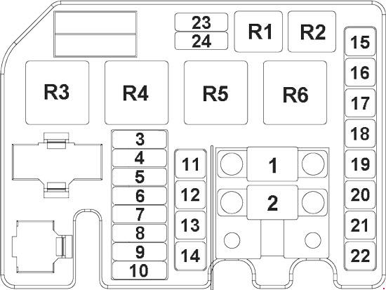
Engine compartment fuse box
| No. |
A |
Function/component |
| 1 | 80 | D4CB / D4BB & Euro 2: E/R Junction Box (RLY. 3). D4BB & Euro 1 : Glow Box |
| 2 | 120 (D4CB) 100 (D4BB) | Alternator (B+). I/P Fuse & Relay Box (Fuse – F7. F12. F14) |
| 3 | 10 | ECM |
| 4 | 10 | Alternator |
| 5 | 10 | Stop Lamp Switch. Stop Signal Relay |
| 6 | 10 | E/R Junction Box (RLY. 1) |
| 7 | 10 | E/R Junction BOX (RLY. 2) |
| 8 | 15 | – |
| 9 | 20 | D4CB: ECM |
| 10 | 10 | D4CB: ECM, Immobilizer Module |
| 11 | 50 | E/R Junction Box (RLY. 4), Ignition Switch |
| 12 | 30 | Engine Control Relay |
| 13 | 50 | E/R Junction Box (Fuse – F16. F17. F18. F19). I/P Fuse & Relay Box (Fuse – F29. F30, F31, Power Connector F3) |
| 14 | 40 | l/P Fuse & Relay Box (Fuse – F1, F16. Tail Lamp Relay) |
| 15 | 30 | E/R Junction Box (RLY. 6) |
| 16 | 30 | – |
| 17 | 40 | – |
| 18 | 30 | – |
| 19 | 40 | – |
| 20 | 30 | l/P Fuse & Relay Box (Blower Relay) |
| 21 | 40 | – |
| 22 | 30 | E/R Junction Box (RLY. 5) |
| 23 | 10 | D4CB: E/R Junction Box (RLY. 2, RLY. 6). Inlet Metering Valve, Stop Lamp Switch |
| 24 | 15 | D4CB: VGT Actuator, E/R Junction Box (RLY. 3) |
| Relays | ||
| R1 | A/C Relay | |
| R2 | Horn Relay | |
| R3 | Condenser Fan Relay | |
| R4 | Fuel Filter Heater Relay | |
| R5 | Start Relay | |
| R6 | Glow Relay | |
WARNING: Terminal and harness assignments for individual connectors will vary depending on vehicle equipment level, model, and market.