GMC C-Series mk3 (Third Generation; 2003 – 2009) – fuse box diagram
Year of production: 2003, 2004, 2005, 2006, 2007, 2008, 2009
Instrument Panel
There are two instrument panel fuse blocks located behind the instrument panel on the passenger’s side of the vehicle.
Fuse block 1
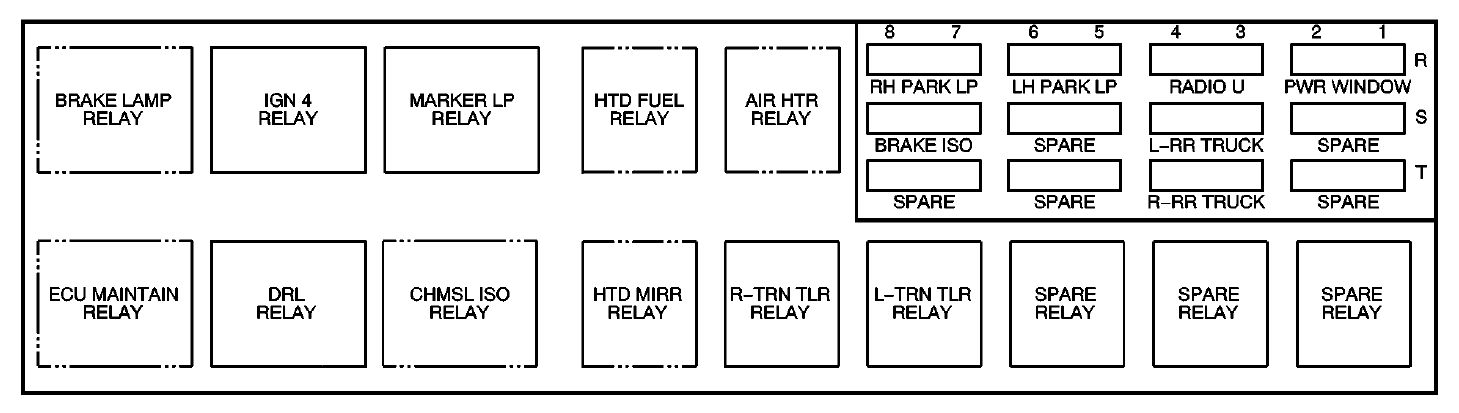
| Fuse | Circuits protected |
| RH PARK LP | Right-hand Parking Lamps |
| LH PARK LP | Left-hand Parking Lamps |
| RADIO U | Radio |
| PWR WINDOW | Power Windows |
| BRAKE ISO | Brake Warning Lamp |
| SPARE | Spare Fuse |
| L-RR TRUCK | Left Rear Trailer Wiring |
| SPARE | Spare Fuse |
| SPARE | Spare Fuse |
| SPARE | Spare Fuse |
| R-RR TRUCK | Right Rear Trailer Wiring |
| SPARE | Spare Fuse |
| Relay | Circuits protected |
| BRAKE LAMP | C4/C5 Brake Lamps, C6/C7/C8 Tractor/Trailer Wiring |
| IGN 4 | Ignition |
| MARKER LP | Sidemarker and Clearance Lamps |
| HTD FUEL | LB7/LG4 Heated Fuel |
| AIR HTR | LG4 Air Heater |
| ECU MAINTAIN | LG4 Electronic Control Unit |
| DRL | Daytime Running Lamps |
| CHMSL ISO | Center High Mounted Stop Lamp |
| HTD MIRR | Heated Mirrors |
| R-TRN TLR | Right Trailer Turn Signal |
| L-TRN TLR | Left Trailer Turn Signal |
| SPARE | Spare Relay |
| SPARE | Spare Relay |
| SPARE | Spare Relay |
Fuse block 2
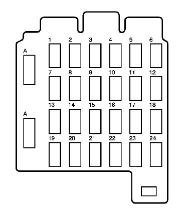
| Circuit Breaker | Usage |
| 1 | Stoplamps |
| 2 | Center High Mounted Stop Lamp |
| 3 | Parking Lamps |
| 4 | Powertrain Control Module |
| 5 | Auxiliary Wiring |
| 6 | Heater/Air Conditioning |
| 7 | Hazard Warning Flashers |
| 8 | Power Post |
| 9 | Courtesy Lamps |
| 10 | Warning Lights, Gages and Indicators |
| 11 | Crank |
| 12 | Rear Axle |
| 13 | Trailer Turn Signals/Hazard Warning Flashers |
| 14 | Radio/Chime |
| 15 | Daytime Running Lamps |
| 16 | Air Bag System |
| 17 | Exterior/Interior Lamps |
| 18 | Parking Brake |
| 19 | Accessory Power |
| 20 | Ignition |
| 21 | Sidemarker Lamps |
| 22 | Turn Signal/Backup Lamps |
| 23 | Transmission |
| 24 | Chassis |
| A | Spare |
| B | Spare |
Underhood Fuse Block
There are two underhood fuse blocks located in the engine compartment, on the
passenger’s side of the vehicle.
Primary Underhood fuse block
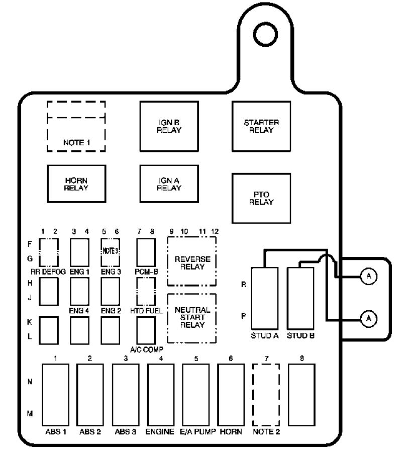
| Relay | Usage |
| NOTE 1 | LG4 Powertrain Control Valve, L18/LB7 Fuel Pump, LG5 Heated Fuel |
| IGN B | Ignition |
| STARTER | Starter |
| HORN | Horn |
| IGN A | Ignition |
| PTO | Power Take-Off |
| REVERSE | Reverse |
| NEUTRAL START | Neutral Start |
| Fuse | Usage |
| RR DEFOG | Rear Defog |
| ENG 1 | Engine 1 |
| ENG 3 | Engine 3 |
| PCM-B | Powertrain Control Module |
| BLANK | Empty |
| ENG 4 | Engine 4 |
| ENG 2 | Engine 2 |
| BLANK | Empty |
| BLANK | Empty |
| BLANK | Empty |
| A/C COMP | Air Conditioning Compressor |
| ABS 1 | Anti-Lock Brake System 1 |
| ABS 2 | Anti-Lock Brake System 2 |
| ABS 3 | Anti-Lock Brake System 3 |
| ENGINE | Engine |
| E/A PUMP | Electronic/Automatic Pump |
| HORN | Horn |
| NOTE 2 | L18/LB7 Fuel, LG4 Powertrain Control Valve, LG5 Electronic Control Module |
| BLANK | Empty |
| STUD A | Spare |
| STUD B | Spare |
Secondary Underhood Fuse Block
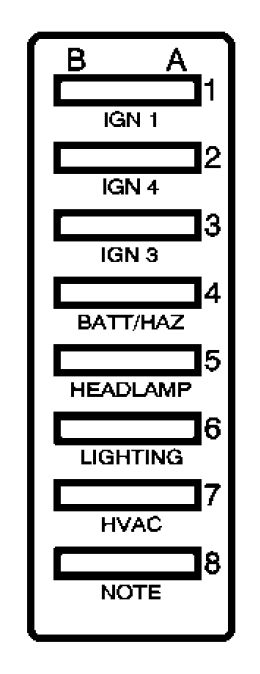
| Fuse | Usage |
| IGN 1 | Ignition 1 |
| IGN 4 | Ignition 4 |
| IGN 3 | Ignition 3 |
| BATT/HAZ | Battery/Hazard Warning Flashers |
| HEADLAMP | Headlamps |
| LIGHTING | Interior/Exterior Lamps |
| HVAC | Comfort Control System |
| NOTE | C4/C5 Electric Brake, C6/C7/C8 Brake Lamps |
WARNING: Terminal and harness assignments for individual connectors will vary depending on vehicle equipment level, model, and market.