
Eagle Talon (1990) – fuse box diagram
Year of production: 1990
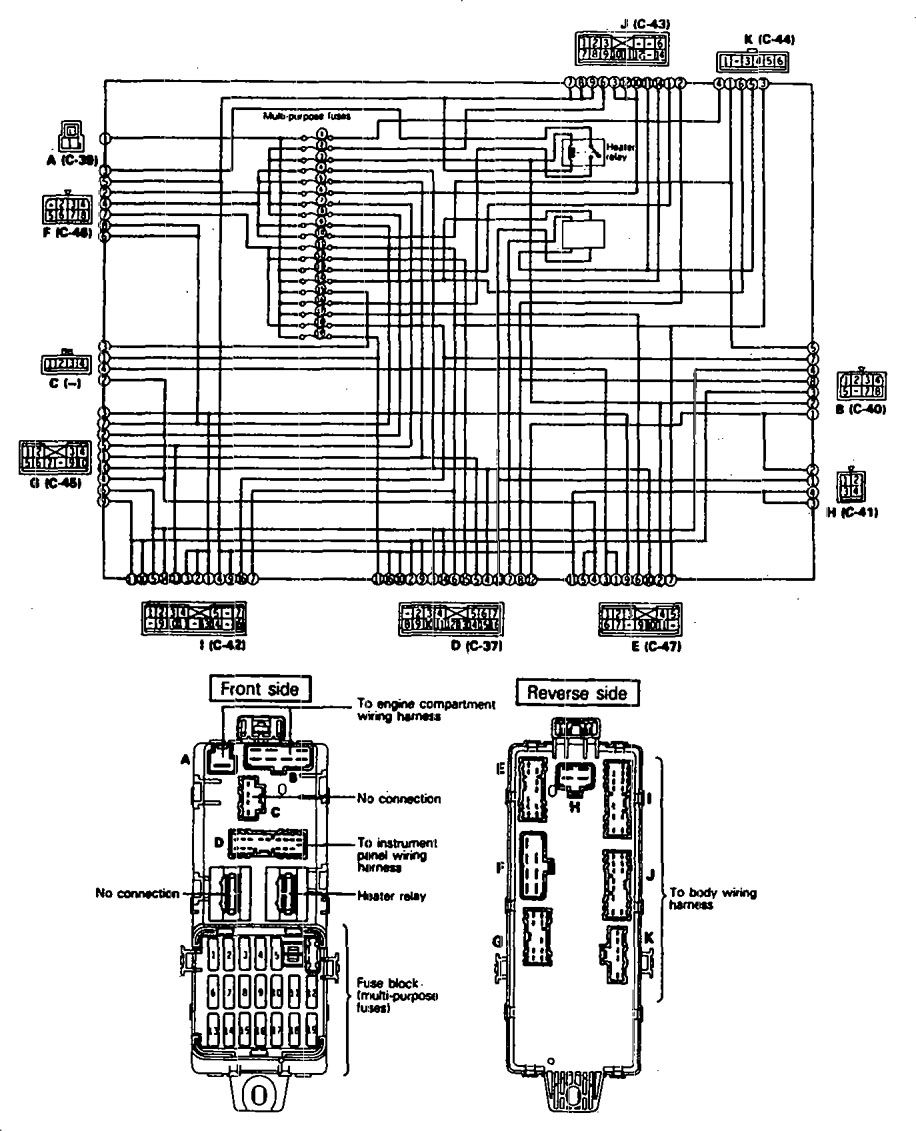
Fuse box diagram

| Power supply circuit | No. | A | Load circuit | |
| Battery | 1 | 10 | Automatic seatbelt control unit, key reminder switch, passing control relay, seatbelt warning buzzer, utillight relay | |
| Ignition switch | IG2 | 2 | — | — |
| 3 | 10 | Air conditioner contlol unit, air conditioner switch, defogger timer, heater relay, power window relay | ||
| ACC | 4 | 10 | Radio | |
| 5 | 15 | Cigarette lighter, remote controlled mirror | ||
| Battery | 6 | 15 | Door lock relay, door lock control unit | |
| Ignition switch | IG2 | 7 | 10 | 4-speed automatic transaxle control unit, auto-cruise control unit <A/T>, combination meter |
| 8 | — | — | ||
| ACC | 9 | 15 | Intermittent wiper relay, wiper motor, washer motor | |
| 10 | 10 | Headlight relay, horn | ||
| IG1 | 11 | 10 | Auto-cruise control unit, auto-cruise control actuator automatic seatbelt contyrol unit, combination meter | |
| 12 | 10 | Tum-signal and hazard flasher unit | ||
| Battery | 13 | — | — | |
| 14 | — | — | ||
| 15 | — | — | ||
| 16 | 30 | Blower motor | ||
| 17 | 15 | Stop light | ||
| Ignition switch | IG1 | 18 | 10 | Back-UP light < M/T>, dome light relay |
| Battery | 19 | 10 | 4-speed automatic transaxle control unit, dome light, door-ajar warning light, foot light, ignition key illumination light, luggage compartment light, MPI control unit, radio | |
WARNING: Terminal and harness assignments for individual connectors will vary depending on vehicle equipment level, model, and market.