Cadillac DTS (2008 – 2011) – fuse box diagram
Year of production: 2008, 2009, 2010, 2011
Underhood Fuse Block
The underhood fuse block is located on the passenger’s side of the engine compartment. Remove the fuse cover and secondary service cover to access the fuse block.
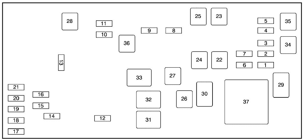
| Fuses | Usage |
| F1 | Engine Control Module (ECM), Crank |
| F2 | Fuel Injectors Odd |
| F3 | Fuel Injectors Even |
| F4 | Air Conditioning Clutch |
| F5 | Air Injection Reactor (AIR) Solenoid |
| F6 | Oxygen Sensor |
| F7 | Emission Device |
| F8 | Transmission, Ignition 1 |
| F9 | Engine Control Module (ECM), Powertrain Control Module (PCM) |
| F10 | Climate Control System, Instrument Panel Cluster Ignition 1 |
| F11 | Airbag System |
| F12 | Horn |
| F13 | Windshield Wiper |
| F14 | Fog Lamps |
| F15 | Right High-Beam Headlamp |
| F16 | Left High-Beam Headlamp |
| F17 | Left Low-Beam Headlamp |
| F18 | Right Low-Beam Headlamp |
| F19 | Windshield Washer Pump Motor |
| F20 | Left Front Cornering Lamp |
| F21 | Right Front Cornering Lamp |
| F22 | Air Pump (J-Case) |
| F23 | Antilock Brake System (ABS) (J-Case) |
| F24 | Starter (J-Case) |
| F25 | Antilock Brake System (ABS) Motor (J-Case) |
| F26 | Cooling Fan 2 (J-Case) |
| F27 | Cooling Fan 1 (J-Case) |
| F28 | Windshield Washer Heater (J-Case) |
| Relays | Usage |
| 29 | Powertrain |
| 30 | Starter |
| 31 | Cooling Fan 2 |
| 32 | Cooling Fan 3 |
| 33 | Cooling Fan 1 |
| 34 | Air Conditioning Clutch |
| 35 | Air Injection Reactor (AIR) Solenoid |
| 36 | Ignition |
| 37 | Air Pump |
Rear Underseat Fuse Block
The rear fuse block is located under the rear seat on the driver’s side. The rear seat cushion must be removed to access the rear fuse block.
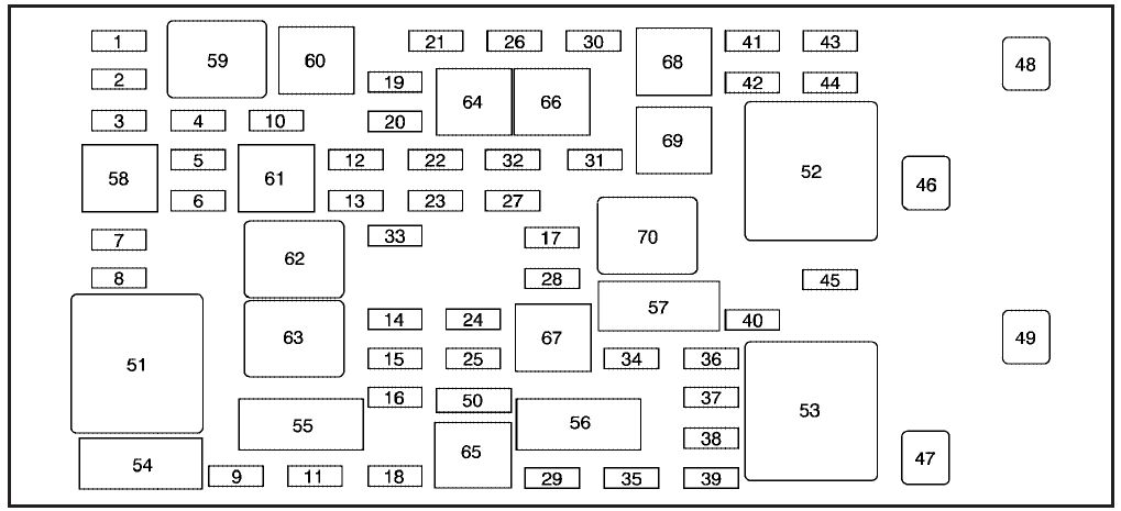
| Fuses | Usage |
| 1 | Fuel Pump |
| 2 | Left Park Lamp |
| 3 | Run 3 – Rear Blower |
| 4 | Right Park Lamp |
| 5 | Engine Control Module (ECM)/Transmission Control Module (TCM) |
| 6 | Memory Module |
| 7 | Right Park Lamp (optional) |
| 8 | Steering Wheel Illumination |
| 9 | Front Heated/Cooled Seat Module |
| 10 | Run 2 – Heated/Cooled Seats, Heated Washer Fluid |
| 11 | Rear Heated Seat Module |
| 12 | RPA Module |
| 13 | PASS-Key® III System |
| 14 | Unlock/Lock Module |
| 15 | Magnetic Ride Control |
| 16 | Daytime Running Lamps (DRL) (optional) |
| 17 | Sunroof |
| 18 | Body Control Module (BCM) Dim |
| 19 | Body Control Module (BCM) |
| 20 | Run 1-Heated Steering Wheel |
| 21 | Ignition Switch |
| 22 | Driver Door Module |
| 23 | Rear Lumbar |
| 24 | Electronic Leveling Control Module |
| 25 | Body Control Module (Left Turn Signal) |
| 26 | Cigarette Lighter, Auxiliary Power Outlet |
| 27 | Navigation |
| 28 | Retained Accessory Power 1 (RAP) |
| 29 | Passenger Door Module |
| 30 | Sensing and Diagnostic Module |
| 31 | Accessory Power Outlets |
| 32 | Body Control Module (BCM) (Inadvertent) |
| 33 | Retained Accessory Power 2 (RAP) |
| 34 | Canister Vent Solenoid |
| 35 | Body Control Module (Courtesy) |
| 36 | Body Control Module (Right Turn Signal) |
| 37 | Trunk Release |
| 38 | Amplifier, Radio |
| 39 | Body Control Module (CHMSL) |
| 40 | Body Control Module |
| 41 | Stoplamp (optional) |
| 42 | OnStar® Module |
| 43 | Body Modules |
| 44 | Radio |
| 45 | Door Unlatch (optional) |
| 46 | Rear Defogger (J-Case) |
| 47 | Electronic Leveling Control Compressor (J-Case) |
| 48 | Blower (J-Case) (optional) |
| 49 | Blower (J-Case) (optional) |
| Resistor | USage |
| 50 | Terminating Resistor |
| Relay | Usage |
| 51 | Front Blower (optional) |
| 52 | Rear Defogger |
| 53 | Electronic Leveling Control Compressor |
| 58 | Park Lamps |
| 59 | Fuel Pump |
| 60 | License Plate Lamp (optional) |
| 61 | Right Park Lamp (optional) |
| 62 | Unlock |
| 63 | Lock |
| 64 | Run |
| 65 | Daytime Running Lamps (DRL) (optional) |
| 66 | Door Unlatch (optional) |
| 67 | Trunk Release |
| 68 | Stoplamp (optional) |
| 69 | Overhead Lamps (optional) |
| 70 | Retained Accessory Power (RAP) |
| Circuit Breakers | Usage |
| 54 | Right Front Seat |
| 55 | Left Front Power Seat |
| 56 | Power Windows |
| 57 | Power Tilt Steering Wheel |
WARNING: Terminal and harness assignments for individual connectors will vary depending on vehicle equipment level, model, and market.