
Year of production: 1998
Instrument Panel Fuse Block
The fuse panel is located inside the glove box, on the left side.
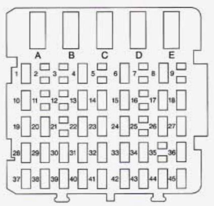
| Circuit Breaker | Usage |
| A | — |
| B | Power Windows/Sunroof |
| C | Rear Defog |
| D | Power Seats |
| Fuse | Usage |
| 1 | — |
| 4 | Ignition Signal — Hot in Run and Start — PCM, BCM U/H Relay |
| 6 | Power Mirrors |
| 8 | Panel Dimming |
| 10 | Ignition Signal — Hot in Run, Unlock and Start — Cluster, Powertrain Control Module, Body Control Module |
| 13 | DRL Module |
| 14 | Interior Lamps |
| 15 | Door Locks |
| 17 | Taillamps, License Lamp |
| 18 | Radio |
| 19 | Heated Mirror |
| 20 | Cruise Control |
| 22 | Clusters |
| 23 | Cigarette Lighter — Auxiliary Power Connection (Power Drop), Data Link |
| 24 | Stoplamps |
| 26 | Parking Lamps |
| 27 | Auxiliary Power Connection (Power Drop) — Hot in ACC and RUN |
| 28 | Crank Signal — Body Control Module, Cluster, Powertrain Control Modules |
| 29 | Ignition Signal — HVAC Control Head |
| 30 | Brake Transmission Shift Interlock (BTSI) |
| 31 | Air Bag |
| 32 | Anti-lock Brake Controls, Body Control Module |
| 33 | Hazard Flashers |
| 34 | — |
| 36 | Ignition Signal — Hot in ACC and Run — Body Control Module |
| 37 | Anti-lock Brake Solenoids |
| 38 | Low Blower |
| 39 | Anti-lock Brakes |
| 40 | Turn Signals |
| 41 | Radio, HVAC Head, Remote Keyless Entry, Cluster |
| 42 | High Blower |
| 43 | — |
| 44 | Audio Steering Wheel Controls |
| 45 | Wipers |
Underhood Electrical Center — Passenger’s Side
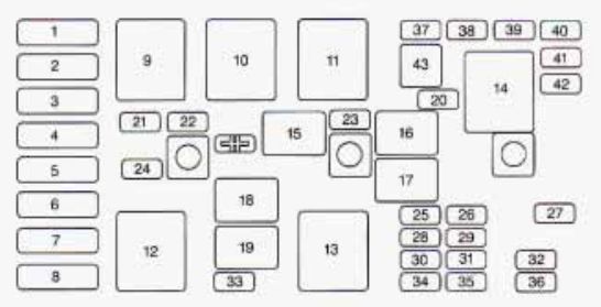
| Fuse | Usage |
| 1 | Cooling Fan |
| 2 | Starter Solenoid |
| 3 | Power Seats, Rear Defog |
| 4 | High Blower, Hazard Flasher, Stoplamps, Power Mirror, Door Locks |
| 5 | Ignition Switch, BTSI, Stoplamps, ABS, Turn Signals, Cluster, Air Bag, DRL Module |
| 6 | Cooling Fan |
| 7 | Interior Lamps, Retained Accessory Power, ABS, Keyless Entry, Data Link, HVAC Head, Cluster, Radio, AUX Power (Power Drop), Cigarette Lighter |
| 8 | Ignition Switch, Wipers, Radio, Steering Wheel Controls, Body Control Module, AUX Power (Power Drop), Power Windows, Sunroof, HVAC Controls, DRL, Rear Defog Relay |
| Relay | Usage |
| 9 | Cooling Fan 2 |
| 10 | Cooling Fan 3 |
| 11 | Starter Solenoid |
| 12 | Cooling Fan 1 |
| 13 | Ignition Main |
| 14 | — |
| 15 | A/C Clutch |
| 16 | Horn |
| 17 | — |
| 18 | — |
| 19 | Fuel Pump |
| Fuse | Usage |
| 20 | — |
| 21 | Generator |
| 22 | ECM |
| 23 | A/C Compressor Clutch |
| 24 | — |
| 25 | Electronic Ignition |
| 26 | Transaxle |
| 27 | Horn |
| 28 | Fuel Injector |
| 29 | Oxygen Sensor |
| 30 | Engine Emissions |
| 31 | — |
| 32 | Headlamp (Right) |
| 33 | Rear Compartment Release |
| 34 | Parking Lamps |
| 35 | Fuel Pump |
| 36 | Headlamp (Left) |
| 37 | Spare |
| 38 | Spare |
| 39 | Spare |
| 40 | Spare |
| 41 | Spare |
| 42 | Spare |
| 43 | Fuse Puller |
| SYMBOL | A/C Commessor Clutch Diode |
WARNING: Terminal and harness assignments for individual connectors will vary depending on vehicle equipment level, model, and market.