Mercury Mariner Hybrid (2006 – 2010) – fuse box diagram
Year of production: 2006, 2007, 2008, 2009, 2010
Passenger compartment fuse panel
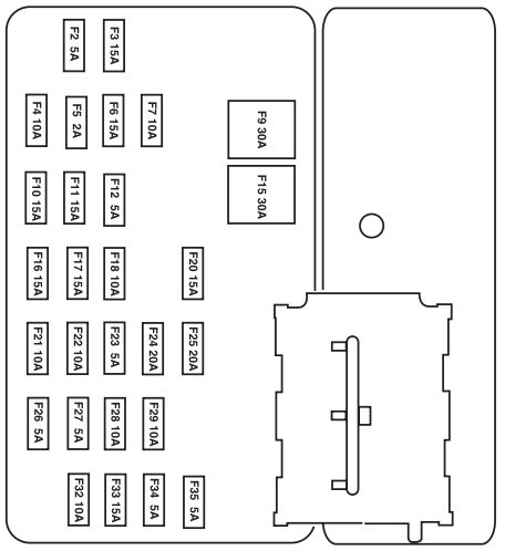
The fuse panel is located on the right-hand side of the center console, by the instrument panel. Remove the panel cover to access the fuses.
| Fuse/relay | Ampere rating [A] | Description |
| 1 | — | Not used |
| 2 | — | Not used |
| 3 | 15* | Front and rear park lamps |
| 4 | 10* | Ignition switch |
| 5 | 2* | Powertrain Control Module (PCM relay), PATS module |
| 6 | 15* | Stop lamps |
| 7 | 10* | Instrument cluster, Power mirror switch, Radio |
| 8 | — | Not used |
| 9 | 300** | Power door locks |
| 10 | 15* | Heated mirrors, Rear defroster switch indicator |
| 11 | 15* | Moon roof |
| 12 | 5* | Radio |
| 13 | — | Not used |
| 14 | — | Not used |
| 15 | 30** | Power windows |
| 16 | 15* | Subwoofer |
| 17 | 15* | Low beams |
| 18 | 10* | 4×4 |
| 19 | — | Not used |
| 20 | 15* | Horn |
| 21 | 10* | Rear wiper motor, Rear wiper washer |
| 22 | 10* | Instrument cluster |
| 23 | — | Not used |
| 24 | 20* | Cigar lighter |
| 25 | 20* | Front wiper motor, Front wiper washer |
| 26 | 5* | Climate control system mode switch |
| 27 | 5* | Traction (high voltage) Battery Control Module (TBCM), Injectors |
| 28 | 10* | Instrument cluster |
| 29 | 10* | Back-up lamps, Reverse park aid |
| 30 | — | Not used |
| 31 | — | Not used |
| 32 | 10* | Spare |
| 33 | 15* | Air bag module |
| 34 | 5* | Brake System Control Module (BSCM), Power Steering Control Module (PSCM) |
| 35 | 5* | 4×4, Heated seats |
| * Mini fuse ** Cartridge fuse | ||
Power distribution box
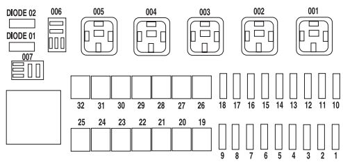
The power distribution box is located in the engine compartment. The power distribution box contains high-current fuses that protect your vehicle’s main electrical systems from overloads.
| Fuse/relay | Ampere rating [A] | Description |
| 1 | 5* | Brake module |
| 2 | 10* | Climate control |
| 3 | 5* | Transaxle Control Module (TCM) |
| 4 | 7,5* | Traction (high voltage) Battery Control Module (TBCM), Powertrain Control Module (PCM) |
| 5 | 5* | Interlock |
| 6 | 15* | PCM power |
| 7 | 15* | Heated Exhaust Gas Oxygen (HEGO) sensors |
| 8 | 10* | TCM VPWR |
| 9 | 20* | Fuel pump |
| 10 | 30* | Bussed power feed to PDB fuses 1, 2, 3, 4 |
| 11 | 20* | Foglamps |
| 12 | 25* | Exterior lighting |
| 13 | 25* | B+ lighting |
| 14 | — | Not used |
| 15 | 20* | Ignition main |
| 16 | 15* | A/C clutch |
| 17 | 20* | Power point |
| 18 | 30* | Injectors, COP (Coil-on-plug) |
| 19 | 40** | Climate control blower |
| 20 | 40** | Cooling fan #1 |
| 21 | 40** | PCM power |
| 22 | 40** | SJB power (Passenger compartment fuse box) power #1 |
| 23 | 40** | SJB power (Passenger compartment fuse box) power #2 |
| 24 | 50** | BSCM #1 |
| 25 | 50** | Power Steering Control Module (PSCM) #1 |
| 26 | 50** | TBCM (high voltage battery) cooling fans and jump start |
| 27 | 40** | Cooling fan #2 |
| 28 | 40** | Rear defroster, Heated mirrors |
| 29 | 20** | Heated seats |
| 30 | 40** | SJB (Passenger compartment fuse box) power #3 |
| 31 | 50** | BSCM #2 |
| 32 | 50** | PSCM #2 |
| 001 | Relay | Power sustain for PCM, TBCM and Transaxle Control Module (TCM) |
| 002 | Relay | PCM power |
| 003 | Relay | Injector |
| 004 | Relay | Auxiliary coolant pump |
| 005 | Relay | Motor/Electronic coolant pump |
| 006 | Relay | Foglamps |
| 007 | Relay | A/C clutch |
| Diode 01 | — | A/C clutch |
| Diode 02 | — | Not used |
| * Mini fuse **Cartridge fuse | ||
Auxiliary relay box
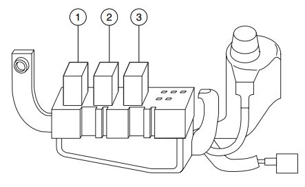
The relay box is located on the radiator support (left of the hood latch).
| Fuse/relay | Description |
| Relay 1 | Driver side cooling fan |
| Relay 2 | Passenger side cooling fan (low-speed) |
| Relay 3 | Passenger side cooling fan (high-speed) |
WARNING: Terminal and harness assignments for individual connectors will vary depending on vehicle equipment level, model, and market