
Bobcat S70 – fuse box diagram
Year of production:
Fuse box
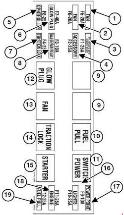
| Number | Protected circuit | Ampers |
| 1 | Fan | 20 |
| 2 | Fan | 20 |
| 3 | BICS/Brakes/Remote Start | 25 |
| 4 | Accessory Back-up Alarm | 25 |
| 5 | Controller | 25 |
| 6 | Glow Plug | 40 |
| 7 | Traction Lock | 25 |
| 8 | Gauge/Fan Relay | 10 |
| 16 | Lights | 25 |
| 17 | Power Point | 10 |
| 18 | Engine/Horn | 25 |
| 19 | Fuel Solenoid | 25 |
| Relay | ||
| 9 | — | |
| 10 | Fuel Solenoid | |
| 11 | Switched Power | |
| 12 | Glow Plug | |
| 13 | Fan | |
| 14 | Traction Lock | |
| 15 | Starter | |
WARNING: Terminal and harness assignments for individual connectors will vary depending on vehicle equipment level, model, and market.