
Mercedes-Benz C280 (1998) – wiring diagrams – instrumentation
Year of productions: 1998
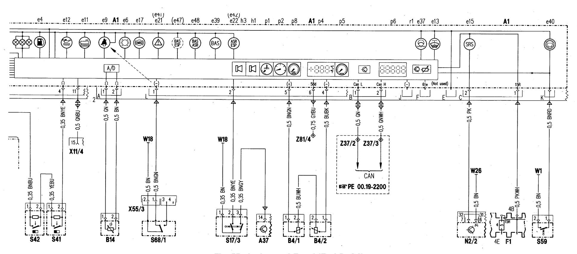
Instrumentation
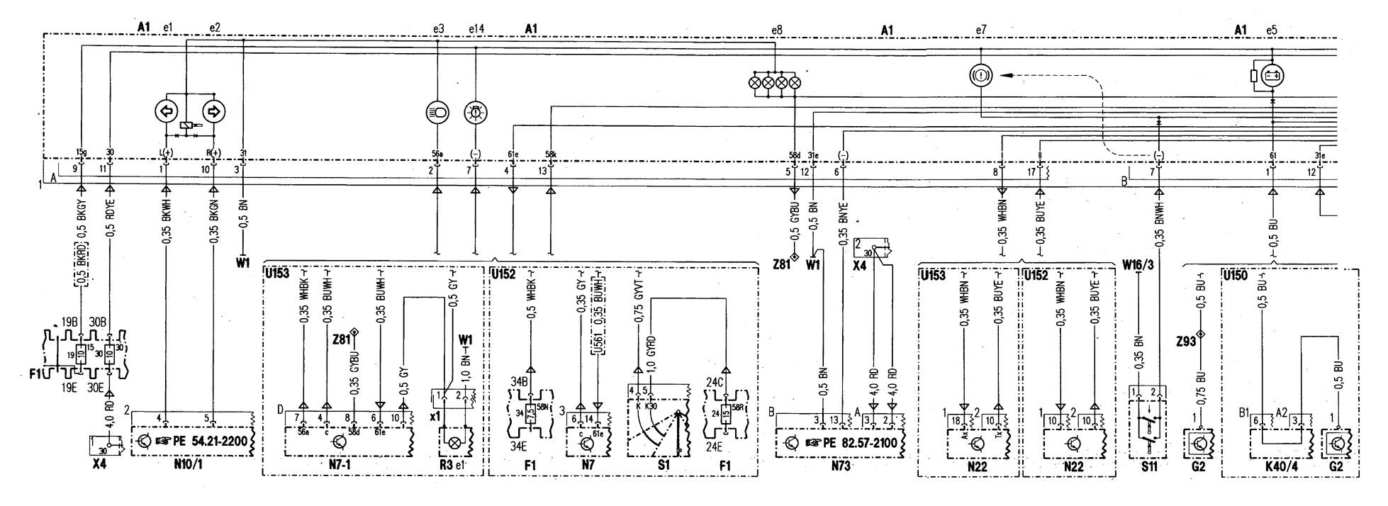
| A1 | Instrument cluster |
| A1e1 | Leh turn signal indicator lamp |
| A1e2 | Right turn signal indicator lamp |
| A1e3 | High beam indicator lamp |
| A1e4 | Fuel reserve indicator lamp |
| A1e5 | Generator charge indicator lamp |
| A1e6 | Brake pad wear indicator lamp |
| A1e7 | Low brake fluid leveVparking brake indicator lamp |
| A1e8 | Instrument illumination |
| A1e9 | Seat belt reminder lamp |
| A1e11 | Low ECL indicator lamp |
| A1e12 | Low engine oil level indicator lamp |
| A1e13 | Low windshield washer fluid level indicator lamp |
| A1e14 | Exterior lamp failure indicator lamp |
| A1e15 | SRS MIL |
| A1e17 | ABSMIL |
| A1e21 | ASR warning lamp |
| A1e22 | ASR MIL |
| A1e39 | Hydraulic fluid level indicator lamp |
| A1e39 | EA warning lamp |
| A1e40 | Steering lock warning lamp |
| A1e41 | ESP warning lamp |
| A1e42 | ESP MIL |
| A1e47 | BAS/ESP MIL |
| A1e48 | BAS!ASR MIL |
| A1h1 | Warning buzzer |
| A1h3 | Speed warning buzzer |
| A1p1 | ECTgauge |
| A1p2 | Fuel level gauge |
| A1p4 | Outside temperature indicator |
| A1p5 | Tachometer |
| A1p6 | Electronic clock |
| A1p8 | Electronic speedometer |
| A1r1 | Instrument iliumination rheostat |
| A37 | PSE control module |
| B4/1 | Leh fuel level sensor |
| B4/2 | Right fuel level sensor |
| B14 | Outside temperature indicator temperature sensor |
| F1 | Fuse and relay box |
| F1f4 | Fuse 4 |
| F1f19 | Fuse 19 |
| F1f24 | Fuse 24 |
| F1f30 | Fuse 30 |
| F1f34 | Fuse 34 |
| G2 | Generator |
| K30 | Auxiliary coolant pump control relay module (REST, engine OFF cooling) |
| K40/4 | Passenger-side fuse and relay module box |
| N2/2 | SAS control module |
| N7 | Exterior lamp failure monitoring module |
| N7-1 | Illumination control module |
| N10/1 | Signal pickup- and activation module (SAM) left front |
| R3 | Front cigar lighter (with ashtray illumination) – 3A |
| R3e1 | lllumina~on – 3A |
| S1 | Exterior lamp switch – 5M |
| U561 | Valid for all except countries with daytime running lights |
| W1 | Main ground (behind instrument cluster) |
| W16/3 | Ground (output ground- component compartment – left) |
| W18 | Ground (lett front. seal crossinember) |
| W26 | Ground (SRS control module) |
| X4 | Terminal block (circuit 30, left footwall) |
| X11/4 | Data link connector (DTC readout) |
| X55/3 | Driver’s seat contact strip |
| Z37/2 | Engine CAN-Bus (low) connector sleeve |
| Z37/3 | Engine CAN-Bus (hig’h) connector sleeve |
| Z81 | Circuit 58d connector sleeve (feed from IC) |
| Z81/4 | Circuit 58d connector steeve (frame floor) |
| Z92 | Circuit 61 e connector sleeve (feed from. instrument cluster – A 1} |
WARNING: Terminal and harness assignments for individual connectors will vary depending on vehicle equipment level, model, and market.