Mercedes-Benz C280 (1998) – wiring diagrams – computer data lines
Year of productions: 1998
Computer data lines
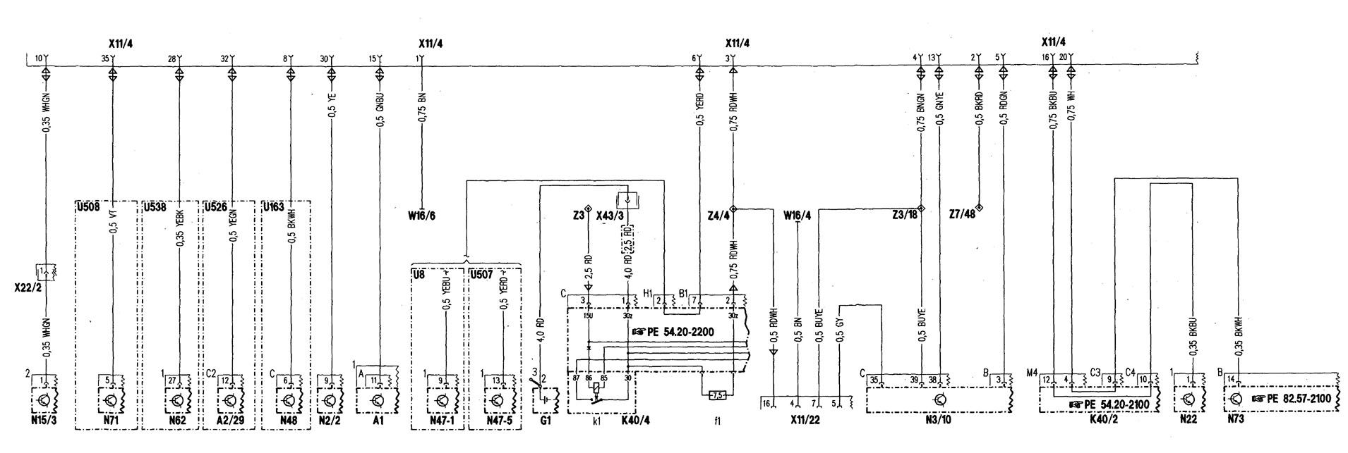
| A1 | Instrument cluster |
| A2/29 | Radio and navigation operating unit, APS |
| G1 | Battery |
| K40/2 | Driver-side fuse and relay module box |
| K40/4 | Passenger-side fuse and relay module box |
| K40/4f1 | Fuse, circuit 30z |
| K40/4k1 | Polarity protection relay |
| N2/2 | SAS control module |
| N3/10 | Engine control module (ME-SF I) |
| N15/3 | Transmission control module |
| N22 | A/C pushbutton control module (Automatic A/C) |
| N47-1 | ASAISPS control module |
| N47-5 | ESP/SPS/BAS control module |
| N48 | BAS control module |
| N52 | Ultrasonic PTS control module |
| N71 | Headlamp range adjustment control module |
| N73 | Electronic ignition lock control module |
| U8 | Valid for ASA |
| U507 | Valid for ESP |
| U508 | Valid for Xenon headlamps |
| U526 | Valid for Auto-Pilot-System |
| U538 | Valid for PTS |
| W16/4 | Ground (output ground – component compartment – right) |
| W16/6 | Ground (electronics ground · component compartment – right) |
| X11/4 | Data link connector (DTC readout) |
| X11/22 | Diagnostic module (OBD II) generic scan tool connector |
| X22/2 | AT/engine connector |
| X43/3 | REST/CL connector, circuit 30Z |
| Z3 | Circuit 15 connector sleeve, feed from fuse F’3123 |
| Z3/18 | Circuit 15 connector sleeve (HFM-SFI, interior/engine) |
| Z4/4 | Circuit 30Z connector sleeve (solder joint in harness) |
| Z7/48 | Circuit 87D2 connector sleeve |
WARNING: Terminal and harness assignments for individual connectors will vary depending on vehicle equipment level, model, and market.