Lifan 620 – fuse box diagram
Year of production:
Junction Box of Dash Board
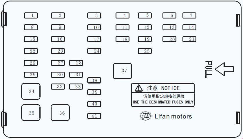
| Number | A | Description |
| 1 | 10 | BCM Central Lock Power Supply |
| 2 | 15 | BCM steering light/warning lamp |
| 3 | 10 | Fuel pump |
| 4 | 15 | Wiper |
| 5 | 15 | Cigarette lighter |
| 6 | 10 | — |
| 7 | 10 | ABS control power supply |
| 8 | 5 | BCM common power supply |
| 9 | 5 | Rear fog light |
| 10 | 15 | Audio-visual system working power |
| 11 | 15 | Electric horn |
| 12 | 5 | Power supply for switching on the audio-visual system |
| 13 | 10 | Reversing lamp |
| 14 | 5 | BCM ignition |
| 15 | 5 | Door/luggage boot lights |
| 16 | 10 | Small light |
| 17 | 15 | — |
| 18 | 10 | Exterior rearview mirror |
| 19 | 10 | A/C controller ignition |
| 20 | 5 | Braking lamp |
| 21 | 10 | Air bag control power |
| 22 | 10 | Roof light |
| 23 | 30 | Power supply for glass regulator |
| 24 | 5 | — |
| 25 | 10 | — |
| 26 | 15 | Power supply for instrument cluster |
| 27 | — | — |
| 28 | — | — |
| 29 | 10 | Power supply for sun roof |
| 30 | 20 | — |
| 31 | — | — |
| 32 | — | — |
| 33 | — | — |
| 34 | 30 | Ignition Am2 |
| 35 | 30 | Ignition Am1 |
| 36 | 30 | Rear defrosting |
| 37 | — | Picker |
| 38 | 30 | — |
| 39 | 15 | Instrument cluster ignition |
| 40 | 20 | — |
| 41 | 15 | Magnetic power supply for power generator/ power generator ECU control ignition coil/ cam sensor/ vehicle speed sensor |
Junction Box for Instrument Panel (Upper Side)
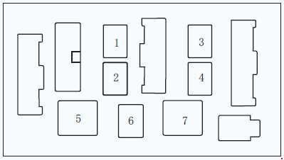
| Number | Description |
| 1 | Electric horn relay |
| 2 | Fuel pump relay |
| 3 | Rear fog light relay |
| 4 | Rear defroster relay |
| 5 | — |
| 6 | — |
| 7 | Accessory power supply relay |
Engine compartment
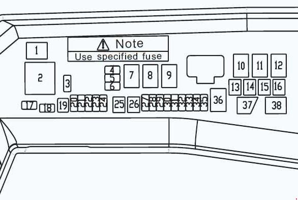
| Number | A | Description |
| 3 | 20 | — |
| 4 | 15 | — |
| 5 | 20 | — |
| 6 | 25 | — |
| 13 | 40 | Blower |
| 14 | 60 | Accessory power supply |
| 15 | 60 | Power supply for driver’s compartment |
| 16 | — | — |
| 17 | 30 | — |
| 18 | 7,5 | — |
| 19 | — | Picker |
| 20 | — | — |
| 21 | — | — |
| 22 | — | — |
| 23 | — | — |
| 24 | — | — |
| 25 | 30 | ABS controller |
| 26 | 30 | ABS controller |
| 27 | 25 | Main relay |
| 28 | 10 | Compressor |
| 29 | 10 | Electronic injection ECU |
| 30 | 25 | High speed fan |
| 31 | 25 | Low speed fan |
| 32 | 5 | Fan speed regulation/high speed/low speed/compressor |
| 33 | 15 | Low beam |
| 34 | 15 | Overtaking/high beam |
| 35 | 15 | Front fog light |
| Relay | ||
| 1 | Front fog light | |
| 2 | Blower | |
| 7 | High speed fan | |
| 8 | Low speed fan | |
| 9 | Speed regulation | |
| 10 | Overtaking light | |
| 11 | High beam | |
| 12 | Low beam | |
| 36 | Main Relay | |
| 37 | Compressor | |
| 38 | Main relay | |
WARNING: Terminal and harness assignments for individual connectors will vary depending on vehicle equipment level, model, and market.