Land Rover Freelander L314 (1997 – 2006) – fuse box diagram
Year of production: 1997, 1998, 1999, 2000, 2001, 2002, 2003, 2004, 2005, 2006
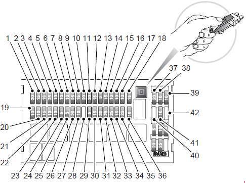
Main fuse box
2004 –
| № |
A |
Circuits protected |
| 1 | 20 | Front screen wash/wipe |
| 2 | 15 | Stop lamps, reversing lamps |
| 3 | 15 | Heated mirrors/Rear screen wash |
| 4 | 25 | Heater blower |
| 5 | 10 | Starter motor |
| 6 | 10 | Cruise control/HDC/Automatic Gearbox start inhibit |
| 7 | 10 | Side lamps – LH |
| 8 | 25 | Driver’s front window lift |
| 9 | 15 | Cigar lighter |
| 10 | 20 | Electric accessories socket |
| 11 | 20 | Heated seats* |
| 12 | 15 | Audio system – Vehicle battery power feed |
| 13 | 5 | Engine immobilisation |
| 14 | 15 | Headlamp main beam – RH |
| 15 | 10 | Door mirrors |
| 16 | 10 | Interior lights/Clock |
| 17 | 10 | Side lamps – RH |
| 18 | 15 | Instruments/Indicators |
| 19 | 10 | Headlamp dipped beam – RH |
| 20 | 10 | Headlamp dipped beam – LH |
| 21 | 15 | Sunroof |
| 22 | 10 | Engine management |
| 23 | 10 | Airbag |
| 24 | 5 | Parking aid |
| 25 | 5 | Anti-lock brakes |
| 26 | 20 | Heated rear window |
| 27 | 10 | Audio system |
| 28 | – | Not used |
| 29 | 5 | Electric windows |
| 30 | 15 | Front fog lamps |
| 31 | 20 | Taildoor glass lift/drop |
| 32 | 25 | Rear window lift – LH |
| 33 | 25 | Rear window lift – RH |
| 34 | 15 | Headlamp main beam – LH |
| 35 | 25 | Passenger front window lift |
| 36 | 10 | Rear fog lamps |
| 37 | 20 | Central door locking |
| 38 | 10 | Rear wiper |
| 39 | 10 | Front fog lamp switch |
| 40 | – | Not used |
| 41 | 10 | Alternator |
| 42 | – | Not used |
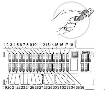
-2003
| № |
A |
Circuits protected |
| 1 | 15 | Rear windshield washers, heated mirrors |
| 2 | 15 | Stop lights, reversing lights |
| 3 | 20 15* |
Windshield wash/wipe |
| 4 | 25 | Heater blower |
| 5 | 10 | Starter motor |
| 6 | 10 | Engine management |
| 7 | 5 10* |
Anti-lock brakes |
| 8 | 15 | Direction indicators |
| 9 | 15 | Audio system |
| 10 | 15 20* |
Cigar lighter |
| 11 | 10 | Audio system |
| 12 | 15 | Sunroof |
| 13 | 20 25* |
Electric accessories socket |
| 14 | 10 | Interior lights, clock, electric mirrors, diagnostic socket |
| 15 | 20 | Central door locking |
| 16 | 10 | Sidelights – RH |
| 17 | 10 | Electric mirrors |
| 18 | 15 | Headlight main beam – RH |
| 19 | 10 | Alternator |
| 20 | 15 | Headlight main beam – LH |
| 21 | 15 | Front fog lights |
| 22 | 10 | Rear fog guard lights |
| 23 | 20 | Rear windshield demister |
| 24 | 10 | Headlight dipped beam – LH |
| 25 | 10 | Headlight dipped beam – RH |
| 26 | 20 | Window – rear LH |
| 27 | 20 | Window – rear RH |
| 28 | 10 | Sidelights – LH |
| 29 | 20 | Heated seats |
| 30 | 10 | Rear windshield wiper |
| 31 | 20 | Taildoor glass lift/drop |
| 32 | 5 20* |
Engine immobilisation Anti-lock brakes* |
| 33 | 25 20* |
Window – front LH |
| 34 | 25 20* |
Window – front RH |
| 35 | 10 | Cruise control, engine immobilisation |
| 36 | 10 | Airbag SRS |
| *-2002 | ||
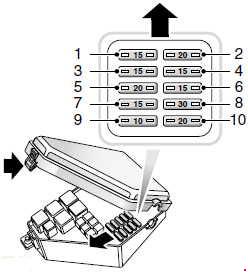
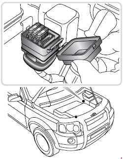
Engine compartment fuse box
The engine compartment fuse box is located on the left side of the engine compartment.
2003-
| № |
A |
Circuits protected |
| 1 | 15 | Engine management |
| 2 | 20 | Engine management |
| 3 | 15 | Engine management |
| 4 | 15 | Air conditioning, cooling fan, automatic gearbox |
| 5 | 20 | Engine management, transmission cooling fan, fuel burning heater |
| 6 | 15 | Horn |
| 7 | 15 | Hazard warning lamps |
| 8 | 30 | Heater blower speed 4 |
| 9 | 10 | Air conditioning |
| 10 | 20 | Fuel system |
-2002

| № |
A |
Circuits protected |
| 1 | 40 | Cooling fan |
| 2 | – | – |
| 3 | 15 | Horn |
| 4 | 15 | Hazard warning lights |
| 5 | 20 | Fuel pump and fuel injectors |
| 6 | 40 | Condenser fan |
| 7 | 30 | Starter solenoid |
| 120 | ALTERNATOR | |
| 60 | IGNITION 1 | |
| 60 | PASSENGER FUSEBOX | |
| 60 | IGNITION 2 | |
| 60 | LIGHTING | |
| 30 | ABS PUMP |
Supplementary fuse box
An additional, supplementary fuse box is fitted to some vehicles, containing fuses for the heated front screen.
| № |
A |
Circuits protected |
| 1 | 30 | LH heated front screen |
| 2 | 30 | RH heated front screen |
| 3 | 7.5 | Switch illumination |
| 4 | – | – |
Fuse specification for vehicles with a PTC system heater

| № |
A |
Circuits protected |
| 1 |
30 |
PTC heater |
| 2 |
30 |
PTC heater |
| 3 |
30 |
PTC heater |
| 4 |
– |
– |
WARNING: Terminal and harness assignments for individual connectors will vary depending on vehicle equipment level, model, and market.