
KIA Stinger (2018) – fuse box diagram
Year of production: 2018
Instrument panel (driver’s side)
Inside the fuse/relay panel covers, you can find the fuse/relay label describing fuse/relay name and capacity.
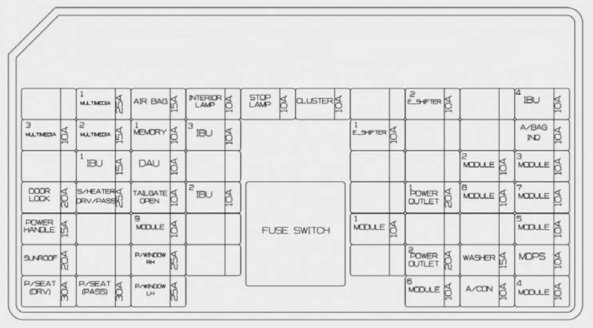
| Fuse name | Fuse rating [A] | Circuit protected |
| MULTI MEDIA 1 | 25 | Low DC-DC Converter (Audio |
| AIR BAG | 15 | SRS (Supplemental Restraint System) Control Module |
| INTERIOR LAMP | 10 | Overhead Console Lamp, Center Room Lamp, Room Lamp, Vanity Lamp Switch Left Handle side/Right Handle side, Luggage Lamp Left Handle side/Right Handle side, Glove Box Lamp, Driver/Passenger Door Mood Lamp, Driver/Passenger Door Lamp, Driver/Passenger Foot Lamp |
| STOP LAMP | 10 | IBU, Stop Lamp Switch |
| CLUSTER | 10 | Instrument Cluster, Head-Up Display |
| E-SHIFTER 2 | 10 | Electronic Auto Transmission Shift Lever (IG1) |
| IBU 4 | 10 | IBU (IG1) |
| MULTI MEDIA 3 | 10 | Instrument Cluster, Head-Up Display, Air Conditioner Switch |
| MULTI MEDIA 2 | 15 | Audio |
| MEMORY 1 | 10 | Air Conditioner Control Module, Air Conditioner Switch, Security Indicator, Head-Up Display |
| IBU 3 | 10 | IBU (B+) |
| E-SHIFTER 1 | 10 | Electronic Auto Transmission Shift Lever (B+) |
| A/BAG IND. | 10 | Instrument Cluster, Passenger Air Bag IND |
| IBU 1 | 15 | IBU (B+) |
| DAU | 10 | Driver Door Module, Driver/Passenger Power Outside Mirror |
| MODULE 2 | 10 | IBU (IG2) |
| MODULE 3 | 10 | Auto Transmission Shift Lever Switch, Driver Door Module, Stop Lamp Switch |
| DOOR LOCK | 20 | Door Lock Relay, Door Unlock Relay, Two Turn Unlock Relay |
| S/HEATER DRV/PASS |
25 | Front Air Ventilation Seat Control Module, Front Seat Warmer Control Module |
| TAIL GATE | 10 | Tail Gate Lid Relay, Fuel Lid Relay, Crash Pad Switch |
| IBU 2 | 10 | Rain Sensor |
| POWER OUTLET 1 | 20 | Front Power Outlet #2 |
| MODULE 8 | 10 | Cooling Fan Controller (BLDC Motor), Around View Monitor, Front Air Ventilation Seat Control Module, Front/Rear Seat Warmer Control Module |
| MODULE 7 | 10 | IBU, ECS Unit, AWD (All Wheel Drive) ECM (Electronic Control Module), Smart Cruise Control Module, Auto Transmission Shift Lever Indicator, Console Switch (Front/Upper), Blind-Spot Collision Warning Unit Left Handle side/Right Handle side, Steering Angle Sensor, Steering Tilt & Telescopic Module, MultiFunction Camera Unit, Crash Pad Switch |
| POWER HANDLE | 15 | Steering Tilt & Telescopic Module |
| MODULE 9 | 10 | Driver Air Lumbar Control Unit |
| MODULE 1 | 10 | Data Link Connector, Console Switch (Upper), Mood Lamp Control Unit |
| MODULE 5 | 10 | Air Conditioner Control Module, Air Conditioner Switch, Audio, Head Lamp Left Handle side/Right Handle side, Low DC-DC Converter (Audio/AMP (Amplifier)), Electro Chromic Mirror, AMP (Amplifier), Driver Integrated memory system Control Module, Front Air Ventilation Seat Control Module, Front/Rear Seat Warmer Control Module |
| SUNROOF | 20 | Sunroof Control Unit (Glass) |
| P/WINDOW RH | 25 | Passenger Power Window Module, Rear Power Window Module Right Handle side |
| POWER OUTLET 2 | 20 | Rear Power Outlet |
| WASHER | 15 | Multifunction Switch |
| MDPS | 10 | MDPS (Motor Driven Power Steering) Unit (R-MDPS (Motor Driven Power Steering)) |
| P/SEAT (DRV) | 30 | Driver Integrated memory system Control Module, Drive Seat Module |
| P/SEAT (PASS) | 30 | Passenger Seat Module |
| P/WINDOW LH | 25 | Driver Power Window Module, Rear Power Window Module Left Handle side |
| MODULE 6 | 10 | IBU, Low DC-DC Converter (Audio/AMP (Amplifier)), Electronic Auto Transmission Shift Lever (SBW (Shift By Wire)), Engine Room Junction Block (RLY. 4 – Power Outlet Relay) |
| A/CON | 10 | Air Conditioner Control Module, Air Conditioner Switch, Engine Room Junction Block (Blower Relay) |
| MODULE 4 | 10 | Head Lamp Left Handle side/Right Handle side, AFS Control Unit, Auto Head Lamp Leveling Device Module |
Engine compartment fuse panel
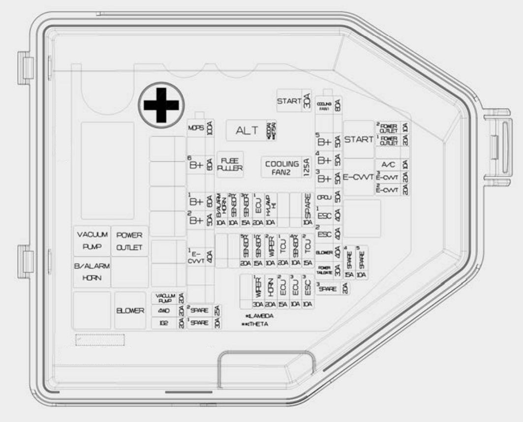
| Fuse name | Fuse rating [A] | Circuit protected |
| ALT | 175 | Alternator, Multi Fuse – COOLING FAN 1 / B+5 / B+4 / B+3 / OPCU / ESC1 / ESC2 / BLOWER / POWER TAIL GATE |
| 200 | ||
| COOLING FAN 2 | 125 | [BLDC (Brushless Direct Current) Motor] Cooling Fan Controller |
| START | 30 | Start Relay |
| COOLING FAN 1 | 80 | [BLDC (Brushless Direct Current) Motor] Cooling Fan Controller |
| B+5 | 50 | Instrument Panel Junction Block (Fuse – STOP LAMP / Leak Current Autocut Device Fuse / INTERIOR LAMP) |
| B+4 | 50 | Instrument Panel Junction Block (Fuse – DOOR LOCK / POWER HANDLE / SUNROOF / P/SEAT (DRV) / P/SEAT (PASS)) |
| B+3 | 50 | Instrument Panel Junction Block (Fuse – S/HEATER DRV/PASS / TAIL GATE / MODULE9 / P/WINDOW RH / P/WINDOW LH) |
| OPCU | 50 | Electric Oil Pump Inverter |
| ESC 1 | 40 | ESC (Electronic Stability Control) Control Module |
| ESC 2 | 40 | ESC (Electronic Stability Control) Control Module, Multipurpose Check Connector |
| BLOWER | 40 | Blower Relay |
| POWER TAIL GATE | 30 | Power Tail Gate Module |
| MDPS | 100 | MDPS (Motor Driven Power Steering) Unit |
| B+6 | 60 | Engine Control Relay, Fuse – HORN / WIPER1 / H/LAMP H / B/ALARM HORN) |
| B+1 | 60 | Instrument Panel Junction Block (Fuse – IBU1 / IBU2) |
| B+2 | 50 | Instrument Panel Junction Block (Fuse – E-SHIFTER1 / MODULE1) |
| E-CVVT 1 | 40 | [THETA II 2.0L T-GDI Engine] E-CVVT Relay |
| VACUUM PUMP | 20 | Vacuum Pump Relay |
| AWD | 20 | AWD (All Wheel Drive) ECM (Electronic Control Module) |
| IG 2 | 20 | IG2 Relay |
| POWER OUTLET 2 | 10 | Front / Rear USB Charger, Front Power Outlet #2 |
| POWER OUTLET 1 | 20 | Front Power Outlet #1 |
| A/C | 10 | Air Conditioner Control Module |
| E-CVVT 3 | 20 | [THETA II 2.0L T-GDI Engine] ECM (Engine Control Module) |
| E-CVVT 2 | 20 | [THETA II 2.0L T-GDI Engine] ECM (Engine Control Module) |
| ESC 3 | 10 | ESC (Electronic Stability Control) Control Module, Multipurpose Check Connector |
| ECU 3 | 10 | ECM (Engine Control Module) |
| ECU 2 | 15 | ECM (Engine Control Module) |
| HORN | 20 | Horn Relay |
| WIPER 1 | 30 | Wiper Power Relay |
| TCU 2 | 15 | TCM (Transmission Control Module) |
| SENSOR 4 | 10 | Brake Vacuum Switch, Vacuum Pump Relay, Electric Oil Pump Inverter |
| TCU 1 | 20 | TCM (Transmission Control Module) |
| WIPER 2 | 10 | IBU (Integrated Body Control Unit), ECM (Electronic Control Module) |
| SENSOR 1 | 15 | Rear Sub Junction Block (Fuel Pump Relay) |
| SENSOR5 | 20 | [THETA II 2.0L T-GDI Engine] Ignition Coil #1/#2/#3/#4 [Lambda II 3.3L T-GDI Engine] Ignition Coil #1/#2/#3/#4/#5/#6 |
| H/LAMP HI | 10 | Head Lamp (High) Relay |
| ECU 1 | 20 | ECM (Engine Control Module) |
| SENSOR 3 | 15 | [THETA II 2.0L T-GDI Engine] Oxygen Sensor (Up) [Lambda II 3.3L T-GDI Engine] Oxygen Sensor #2/#4 |
| SENSOR 2 | 10 | [THETA II 2.0L T-GDI Engine] Electronic Thermostat, Oil Control Valve, Purge Control Solenoid Valve, RCV (Recirculation Valve Control) Control Solenoid Valve, Canister Close Valve
[Lambda II 3.3L T-GDI Engine] Electronic Thermostat, Oil Pressure Solenoid Valve, Oil Control Valve #1/#2/#3/#4 (Intake/Exhaust), RCV (Recirculation Valve Control) Control Solenoid Valve, Purge Control Solenoid Valve, Canister Close Valve |
| B/ALARM HORN | 10 | Burglar Alarm Horn Relay |
Relay
| Relay name | Type |
| Vacuum Pump Relay | ISO HC MICRO |
| B/Alarm Horn Relay | ISO MICRO |
| Power Outlet Relay | ISO HC MICRO |
| Blower Relay | ISO HC MICRO |
| Start Relay | ISO HC MICRO |
| E-CVVT Relay (G4KL) | ISO MICRO |
Rear fuse box panel

| Fuse name | Ampere rating [A] | Circuit protected |
| ECS | 15 | ECS (Electronic Control Suspension) Unit |
| S/HEATER REAR |
20 | Rear Seat Warmer Control Module |
| HEATED MIRROR |
10 | Air Conditioner Switch, Driver/Passenger Power Outside Mirror |
| FUEL PUMP | 20 | Fuel Pump Relay |
| SPARE1 | 10 | — |
| SPARE2 | 15 | — |
| SPARE3 | 15 | — |
| REAR HEATED | 30 | Rear Heated Relay |
| AMP 2 | 25 | AMP (Amplifier) (MOBIS/PREMIUM) |
| SPARE4 | 15 | — |
| AMP 1 | 30 | Low DC-DC Converter (AMP (Amplifier)) |
| IG 1 | 40 | IG1/ACC Relay |
Battery terminal cover
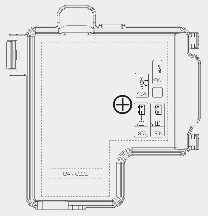
| Fuse name | Ampere rating [A] | Circuit protected |
| B+1 | 80 | Rear Sub Junction Block (Fuse – FUEL PUMP / REAR HEATED/ AMP1) |
| B+2 | 80 | Rear Sub Junction Block (Fuse – ECS / S/HEATER REAR / IG1) |
| START | 40 | Engine Room Junction Block (Power Outlet Relay), Fuse -START / ECU2 / TCU1) |
| AMS | 10 | Battery Sensor |
WARNING: Terminal and harness assignments for individual connectors will vary depending on vehicle equipment level, model, and marke