Iveco Turbo Daily II mk2 (1989 – 1999) – fuse box diagram
Year of production: 1989, 1990, 1991, 1992, 1993, 1994, 1995, 1996, 1997, 1998, 1999
Relay and fuse box in passenger compartment
Located on the driver’s left hand side. Access is gained by opening the door.
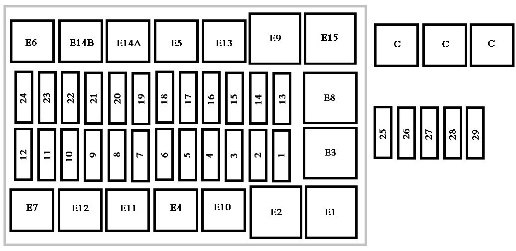
| Fuse | Ampere rating [A] | Description |
| 1 | 5 | Lh front parking light – Lh number plate light- Rh rear parking light – Rh front and Lh rear marker lights – Dashboard. |
| 2 | 5 | Rh front parking light – Rh number plate light – Lh rear parking light – Lh front and Rh rear marker lights. |
| 3 | 7,5 | Lh low beam light |
| 4 | 7,5 | Rh low beam light |
| 5 | 7,5 | Lh high beam light |
| 6 | 7,5 | Rh high beam light |
| 7 | 3 | Electronic speedometer or tachograph |
| 8 | 5 | Brake – instrument – telltale failure |
| 9 | 10 | Fog headlights |
| 10 | 3 | Rear fog lamps. |
| 11 | 5 | Interior lighting (bus) |
| 12 | 7,5 | Not used |
| 13 | 10 | Hazard lights |
| 14 | 5 | Tractor unit turn signal lights |
| 15 | 3 | Engine stop |
| 16 | 7,5 | Reversing lights -stop lights |
| 17 | 10 | Horns |
| 18 | 7,5 | Interior lighting – Cigar lighter |
| 19 | 15 | Heated fuel oil filter. |
| 20 | 10 | Windscreen wiper- Windscreen washer pump |
| 21 | 15 | Electric heater – Electromagnetic fan. |
| 22 | 7,5 | Push switch lighting – flashing light |
| 23 | 25 | Power window – Electromagnetic fan |
| 24 | 10 | Emergency control pushbutton (Bus) |
| 25 | 20 | Air conditioning |
| 26 | 20 | Air conditioning |
| 27 | 25 | Air conditioning |
| 28 | 25 | Electric heater |
| 29 | 40 | Thermostarter control unit |
Relays
| Relays | Description |
| E1 | Low beam lights (switch contacts) |
| E2 | High beam lights (N.o. contact) |
| E3 | Users cutoff during starting stage (N.o. contact) |
| E4 | Fog lamps (switch contacts) |
| E5 | Heated fuel oil filter |
| E6 | Emergency control unit |
| E7 | Day lights + fog lamps |
| E8 | Horns (N.o. contact) |
| E9 | Windscreen wiper intermittent |
| E10 | Flashing light (N.o. contact) |
| E11 | Diode for emergency control unit (with day lights) |
| E12 | Not used |
| E13 | Brake system failure (switch contact) |
| E14A | Emergency control unit (with day lights) |
| E14B | Emergency control unit (with day lights) |
| E15 | Direction indicators – single charge emergency |
| C | Air conditioning |
| N.o.·= Normally open | |
Fuses and relays in engine compartment
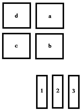
| Fuse | Ampere rating [A] | Description |
| 1 | 30 | Electro-hidraulic assembly (Power Pack) |
| 2 | 20 | Electronic control unit (from battery positive) |
| 3 | 20 | Electronic control unit (lock and key protection) |
| Relay | Description |
| a | Circuit protection diode casing |
| b | Optical indicator ON button |
| c | Reversing light |
| d | Buzzer (acoustic indicator) |
WARNING: Terminal and harness assignments for individual connectors will vary depending on vehicle equipment level, model, and market.