
Year of production: 2004
Passenger compartment fuse panel
The fuse panel is located below and to the left of the steering wheel by the brake pedal.
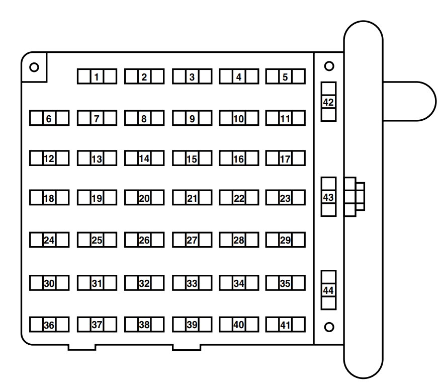
| Fuses/Relay locaction | Ampere rating [A] | Passenger Compartment Fuse panel Description |
| 1 | 5 | 4–Wheel Anti–lock Brake System (4WABS) module |
| 2 | 10 | Remote Keyless Entry (RKE), O/D cancel, Low vacuum (Diesel engine only) |
| 3 | 15 | Trip computer, Radio, Instrument illumination, Video Cassette Player (VCP) and video screens, Overhead console |
| 4 | 15 | Modified vehicle, Courtesy lamps |
| 5 | 30 | Power lock switches, Power locks without RKE |
| 6 | 10 | Brake-shift interlock, Speed control (gasoline engine only) |
| 7 | 10 | Multi-function switch, Turn signals |
| 8 | 30 | Radio capacitor(s), Ignition coil, Powertrain Control Module (PCM) diode, PCM power relay, Auxiliary PCM (APCM) (Diesel engine only) |
| 9 | 30 | Wiper control module, Windshield wiper motor |
| 10 | 20 | Main light switch, Park lamps, License lamp (external lamps), Multi-function switch (flash-to-pass) |
| 11 | 15 | Multi-function switch (hazards), Brake lamp switch, Brake lamps |
| 12 | 15 | Back-up lamps, Auxiliary battery relay (gasoline engine only), Trailer tow relay |
| 13 | 15 | Blend door actuator, A/C heater, Function selector switch |
| 14 | 5 | Instrument cluster |
| 15 | 5 | Trailer battery charge relay, Cluster, Daytime Running Lamps (DRL) module |
| 16 | 30 | Power seats |
| 17 | 5 | Power mirrors |
| 18 | — | Not used |
| 19 | — | Not used |
| 20 | 10 | Restraints |
| 21 | — | Not used |
| 22 | 15 | Memory power radio, Rear seat video control unit, Battery saver relay, Instrument cluster, Courtesy lamp relay, Accessory delay relay |
| 23 | 20 | Power locks w/RKE |
| 24 | — | Not used |
| 25 | 10 | Left headlamp (low beam) |
| 26 | 20 | Cigar lighter, Diagnostics |
| 27 | 5 | Radio |
| 28 | — | Not used |
| 29 | 20 | Power point #4 (console) |
| 30 | 15 | Headlamps (high beam indicator) |
| 31 | 10 | Right headlamp (low beam) |
| 32 | 20 | Power point #1 (instrument panel) |
| 33 | 20 | Starter solenoid (gasoline engine only)/Start relay (diesel engine only) |
| 34 | 20 | Power point #3 (console) |
| 35 | 30 | Modified vehicle |
| 36 | 5 | (Cluster, A/C, Illumination, Radio) |
| 37 | — | Not used |
| 38 | — | Not used |
| 39 | 10 | Trailer tow electric brake, Center High-Mounted Stop Lamp (CHMSL), Brake lamps |
| 40 | 20 | Power point #2 (2nd row seating position – driver side) |
| 41 | 30 | Modified vehicle |
| 42 | — | Not used |
| 43 | 20 circuit breaker | Power windows |
| 44 | — | Not used |
Power distribution box
The power distribution box is located in the engine compartment. The power distribution box contains high-current fuses that protect your vehicle’s main electrical systems from overloads.

| Fuse/Relay Location | Ampere rating [A] | Power Distribution Box Discription |
| 1 | — | Powertrain Control Module (PCM) diode |
| 2 | — | Alternative Fuel Control Module (AFCM) diode (Natural gas vehicle only) |
| 3 | 10* | Daytime Running Lamps (DRL) module, A/C clutch |
| 4 | 20* | Natural Gas Vehicle (NGV) tank solenoids (natural gas vehicle only) |
| 5 | 15* | Horn relay |
| 6 | 2* | Brake pressure switch |
| 7 | 60** | Ignition switch, Fuse panel, Accessory delay |
| 8 | 40** | Trailer battery charge relay |
| 9 | 50** | Modified vehicle power |
| 10 | 30** | Electric brake controller |
| 11 | 60** | 4-Wheel Anti-lock Brake System (4WABS) |
| 12 | 60** | I/P fuses 29, 34, 35, 40 and 41 |
| 13 | 20** | Fuel pump relay |
| 14 | 50** | Auxiliary blower relay |
| 15 | 30** | Main light switch |
| 16 | — | Not used |
| 17 | 50** | Blower motor relay (blower motor) |
| 18 | 60** | Engine compartment fuses 3, 5, 23 and 26, Instrument panel fuses 26 and 32, Diesel start relay (Diesel engine only |
| 19 | 50** | IDM relay (Diesel engine only) |
| 20 | 60** | Auxiliary battery relay (gasoline engine only), PDB fuses 8 and 24 (Diesel engine only) |
| 21 | 30** | PCM power relay, PDB fuse 27 |
| 22 | 60** | I/P fuses 4, 5, 10, 11, 16, 17, 22 and 23 |
| 23 | 10* | Alternator |
| 24 | 20* | Trailer tow running lamps and back-up lamp relays |
| 25 | — | Not used |
| 26 | 20* | Trailer tow turn signals |
| 27 | 10* | PCM |
| 28 | — | Not used |
| A | — | Fuel pump relay |
| B | — | Horn relay |
| C | — | Trailer back-up lamps relay |
| D | — | Trailer running lamps relay |
| E | — | Trailer battery charge relay |
| F | — | IDM relay (Diesel only) |
| G | — | PCM relay |
| H | — | Blower motor relay |
| J | — | Accessory delay relay |
| K | — | Start relay (Diesel only) |
| * Mini fuses** Maxi fuses | ||
Relay modules
Instrument panel relay module
The instrument panel relay module is located behind the radio in the center of the instrument panel.
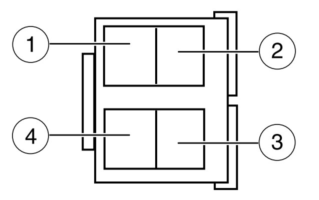
| Relays location | Description |
| 1 | Interior lamps |
| 2 | Open |
| 3 | Roof marker lamps |
| 4 | Battery saver |
Engine compartment relay module
The engine compartment relay module is located in one of two places depending on which type of engine your vehicle is equipped with:
• Gasoline engine: driver side of the engine compartment above the brake master cylinder
• Diesel engine: passenger side of the engine compartment behind the power distribution box
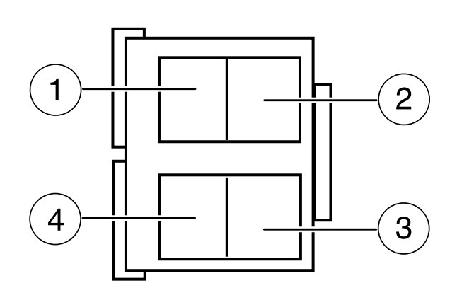
| Relay location | Description |
| 1 | Trailer tow left turn |
| 2 | A/C control |
| 3 | PCM back-up lamp |
| 4 | Trailer tow right turn |
WARNING: Terminal and harness assignments for individual connectors will vary depending on vehicle equipment level, model, and market.