Daewoo Espero – fuse box diagram
Year of production:
Fuse box
The box is located to the right of the steering column under a cover.
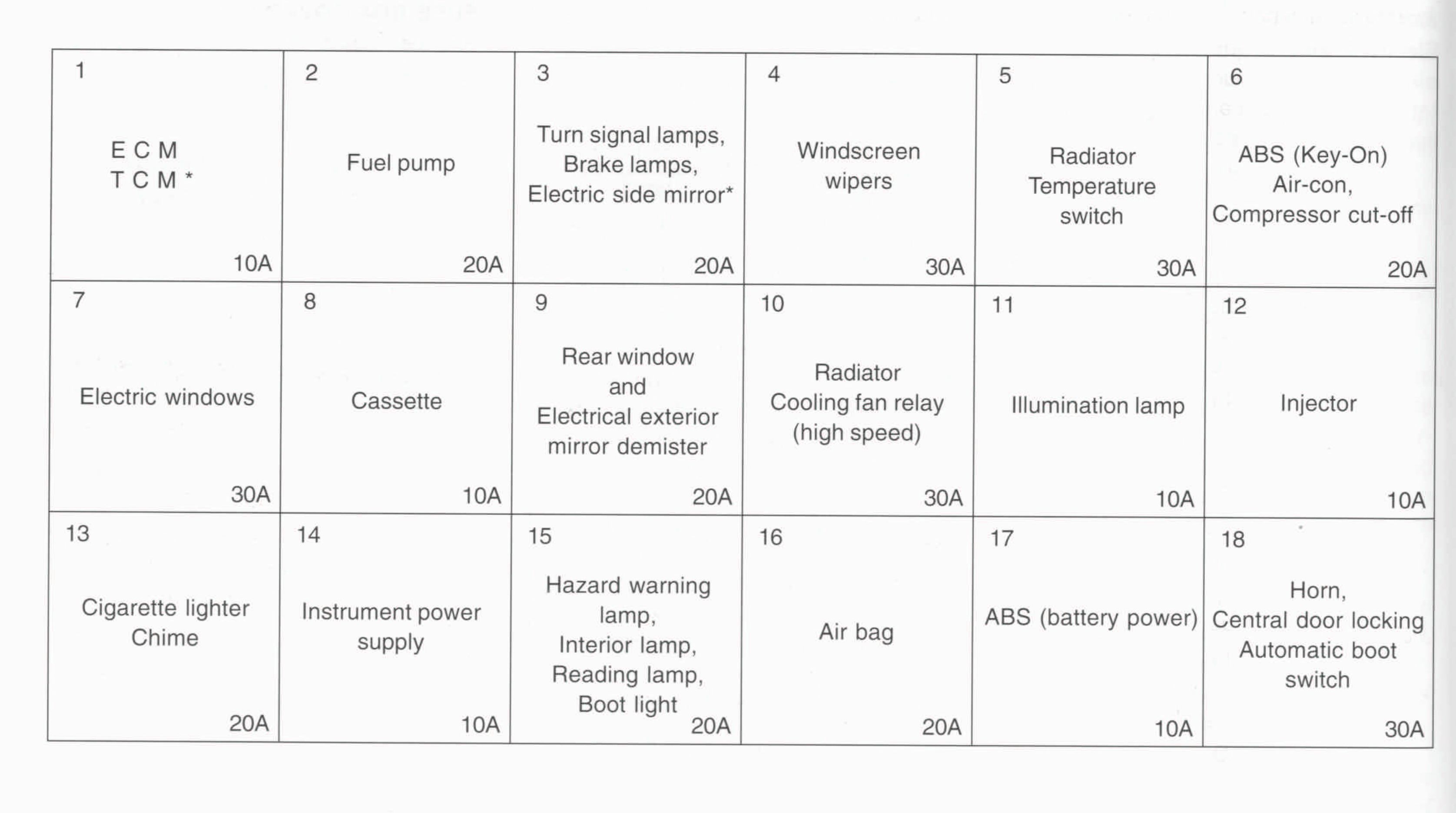
| № | A | Component |
|---|---|---|
| 1 | 10 | ECM, TCM* |
| 2 | 20 | Fuel pump |
| 3 | 20 | Turn signal lamps, brake lamps, electric side mirror* |
| 4 | 30 | Windscreen wipers |
| 5 | 30 | Radiator Temperature switch |
| 6 | 20 | ABS (Key-On), Air-com, Compressor cut-off |
| 7 | 30 | Electric windows |
| 8 | 10 | Cassette |
| 9 | 20 | Rear window and Electric exterior mirror dernister |
| 10 | 30 | Radiator Cooling fan relay (high speed) |
| 11 | 10 | Illumination lamp |
| 12 | 10 | Injector |
| 13 | 20 | Cigarette lighter Chime |
| 14 | 10 | Instrument power supply |
| 15 | 20 | Hazard warning lamp, Interior lamp, Reading lamp, Boot lamp |
| 16 | 20 | Air bag |
| 17 | 10 | ABS (battery power) |
| 18 | 30 | Horn, Central door locking, Automatic boot switch |
Engine compartment
The main relay box is located on the front wheel housing next to the battery in the engine compartment.
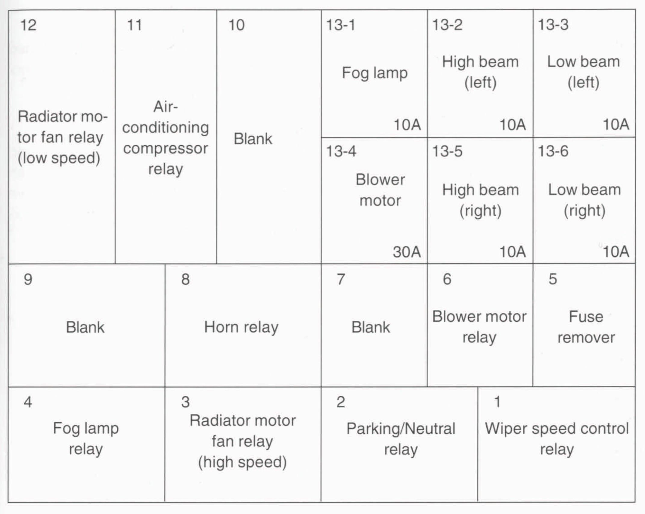
| № | A | Component |
| 1 | Wiper speed control relay | |
| 2 | Parking/Neutral relay | |
| 3 | Radiator motor fan relay (high speed) | |
| 4 | Fog lamp relay | |
| 5 | Fuse remover | |
| 6 | Blower motor relay | |
| 7 | — | |
| 8 | Horn relay | |
| 9 | — | |
| 10 | — | |
| 11 | Air-conditioning compressor relay | |
| 12 | Radiator motor fan relay (low speed) | |
| 13-1 | 10 | Fog lamo |
| 13-2 | 10 | High beam (left) |
| 13-3 | 10 | Low beam (left) |
| 13-4 | 30 | Blower motor |
| 13-5 | 10 | High beam (right) |
| 13-6 | 10 | Low beam (right) |
Auxiliary relay box
Auxiliary relay box is located in the lefthand footwell.
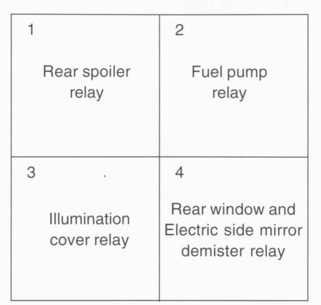
WARNING: Terminal and harness assignments for individual connectors will vary depending on vehicle equipment level, model, and market.