Citroen C4 Cactus (from 2014) – fuse box diagram
Year of production: 2014, 2015, 2016, 2017, 2018
Dashboard fuses
The two fuseboxes are placed in the lower dashboard, at glove box.
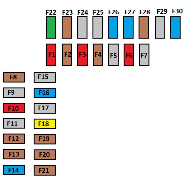
Left hand fusebox
| Fuse | Ampere rating [A] | Functions |
| F01 | 10 | Brake pedal (switch 2), Stop & Start |
| F02 | 5 | Headlamp beam height adjuster, additional heater (Diesel), parking sensor, diagnostic socket, door mirrors (electric adjustment) |
| F03 | 10 | Diesel additive pump, electric power steering, clutch pedal (switch) |
| F04 | 5 | Rain and sunshine sensor |
| F06 | 10 | Brake pedal (switch 1), diagnostic socket |
| F08 | 5 | Top of steering column with steering mounted controls |
| F10 | 10 | Emergency call/ Assistance call |
| F12 | 5 | Stop & Start, ABS, ESC |
| F13 | 5 | Parking sensor, reversing camera |
| F14 | 15 | Electronic gearbox, switch panel (below the touch screen tablet), air conditioning, touch screen tablet |
| F16 | 15 | 12 Volt socket |
| F18 | 20 | Radio |
| F19 | 15 | Seat belt unfasten warning |
| F20 | 5 | Airbags |
| F21 | 5 | Instrument panel |
| F22 | 30 | Locks |
| F23 | 5 | Courtesy lamp, map reading lamp |
| F26 | 15 | Horn |
| F27 | 15 | Front and rear screenwash |
| F28 | 5 | Ignition switch |
| F30 | 15 | Rear wiper |
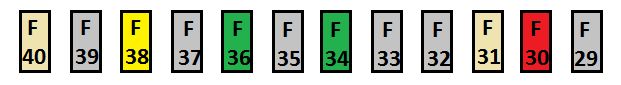
Right hand fuse box
| Fuse | Ampere rating [A] | Functions |
| F30 | 10 | Heated mirrors |
| F31 | 25 | Heated rear screen |
| F34 | 30 | Front electric windows |
| F36 | 30 | Heated front seats |
| F38 | 20 | Trailer interface unit |
| F40 | 25 | Trailer interface unit |
Fuse box in engine compartment
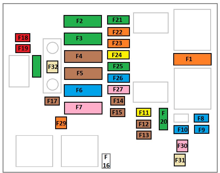
| Fuse | Ampere rating [A] | Functions |
| F1 | 40 | Air conditioning |
| F2 | 30/40 | Stop & Start |
| F3 | 30 | Passenger compartment fusebox |
| F4 | 70 | Passenger compartment fusebox |
| F5 | 70 | Buil-in System Interface (BSI) |
| F6 | 60 | Cooling fan assembly |
| F7 | 80 | Buil-in System Interface (BSI) |
| F8 | 15 | Engine management, petrol pump |
| F9 | 15 | Engine management |
| F10 | 15 | Engine management |
| F11 | 20 | Engine management |
| F12 | 5 | Cooling fan assembly |
| F13 | 5 | Buil-in System Interface (BSI) |
| F14 | 5 | Battery charge unit (non Stop & start engine) |
| F15 | 5 | Stop & Start |
| F17 | 5 | Buil-in System Interface (BSI) |
| F18 | 10 | Right hand main beam headlamp |
| F19 | 10 | Left hand main beam headlamp |
| F20 | 30 | Engine management |
| F21 | 30 | Starter motor |
| F22 | 40 | Electronic gearbox |
| F23 | 40 | ABS, ESC |
| F24 | 20 | ABS, ESC |
| F25 | 30 | Passenger compartment fusebox |
| F26 | 15 | Electronic gearbox |
| F27 | 25 | Buil-in System Interface (BSI) |
| F28 | 30 | Diesel emission control system (AdBlue) |
| F29 | 40 | Windscreen wipers |
| F30 | 80 | Preheater control unit |
| F31 | 100 | Additional heater (Diesel) |
| F32 | 80 | Electric power steering |
WARNING: Terminal and harness assignments for individual connectors will vary depending on vehicle equipment level, model, and market.