Year of production: 2003, 2004
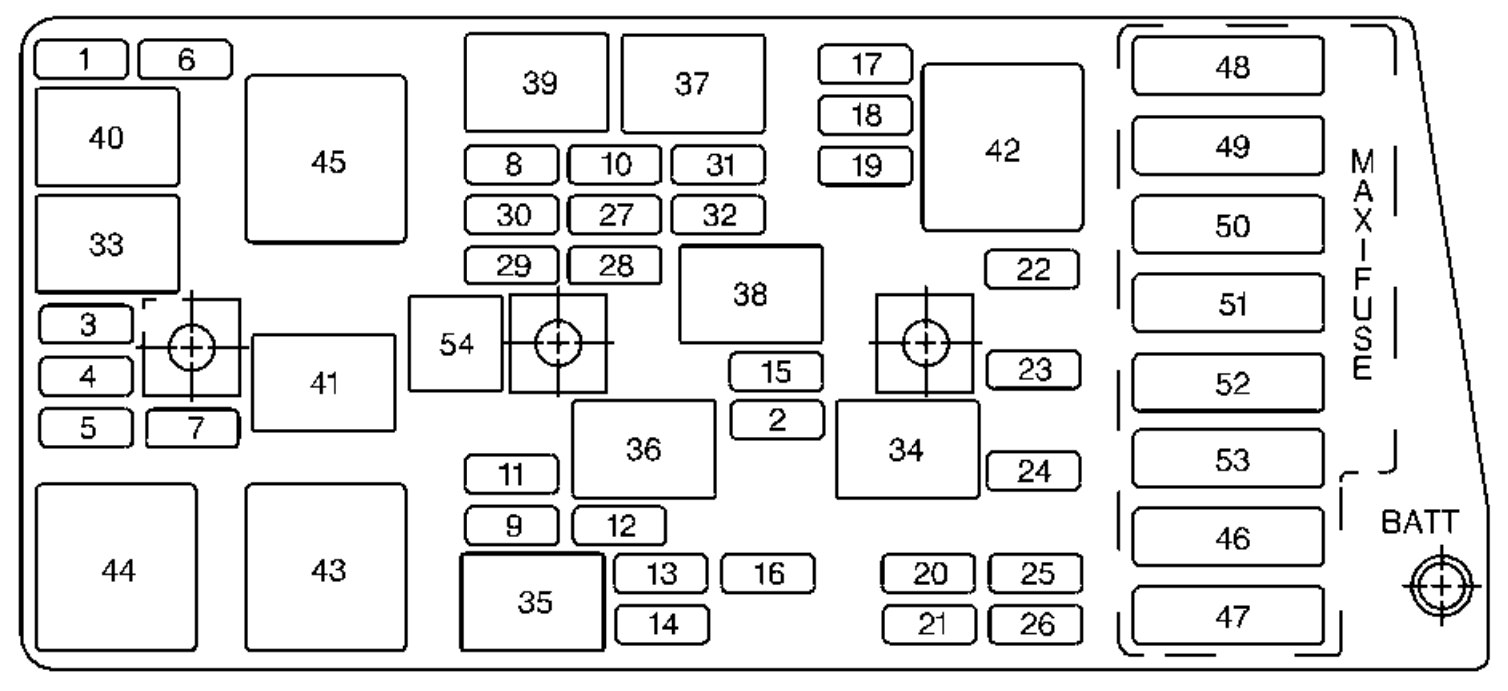
Instrument panel fuse block
The interior fuse center is on the right side of your instrument panel. Turn the knob and pull the door to access the fuses.
instrument panel
| Fuses | Usage |
| 1 | Console Cigarette Lighter |
| 2 | Monitored (Inadvertent) Load Control |
| 3 | Lumbar Seat |
| 4 | Driver Seat Control Module |
| 5 | Radio, Compact Disc Player |
| 6 | Parking Lamps, Taillamps |
| 7 | Cigarette Lighter |
| 8 | Stoplamp, Hazard Flashers |
| 9 | Body Control Module |
| 10 | Windshield Wiper/Washer |
| 11 | Accessory Power |
| 12 | Blank |
| 13 | Body Control Module – Ignition 1 |
| 14 | Crank |
| 15 | Hazard/Turn Signal |
| 16 | Air Bag |
| 17 | Tonneau Release |
| 18 | HVAC Controls |
| 19 | Instrument Panel Control |
| 20 | Cruise Control |
| 21 | Automatic Transmission Shift Lock Control System and Inside Rearview Mirror |
| 22 | Body Control Module – Ignition 3 |
| 23 | Body Control Module – Ignition 2 |
| 24 | Radio Antenna |
| 25 | Body Control Module – Ignition I, Instrument Panel Control |
| 26 | Hatch/Trunk Release |
| 27 | HVAC Controls |
| 28 | Bose Speakers |
| 29 | Diagnostic |
| 30 | Right Door Control Module |
| 31 | Power Feed Door Right |
| 32 | Fuel Tank Door |
| 33 | Door Control Module Left |
| 34 | Power Feed Door Left |
| 44 | Ignition 1 |
| 48 | Rear Defogger |
| 49 | Blank |
| 50 | Ignition 2 |
| 51 | Blower Motor |
| 52 | Starter |
| 53 | Blank |
| Relay | Usage |
| 37 | Monitored (Inadvertent) Load Control |
| 38 | Right Daytime Running Lamp |
| 39 | Hatch/Trunk Release |
| 40 | Left Daytime Running Lamp |
| 41 | Tonneau Release |
| 42 | Courtesy Lamps |
| 43 | Automatic Lamp Control Parking Lamps |
| 44 | Automatic Lamp Control Headlamps |
| 45 | Bose Speaker |
| 46 | Rear Defogger |
| Circuit Breaker | Usage |
| 35 | Driver Power Seat |
| 36 | Passenger Power Seat |
| 54 | Headlamps |
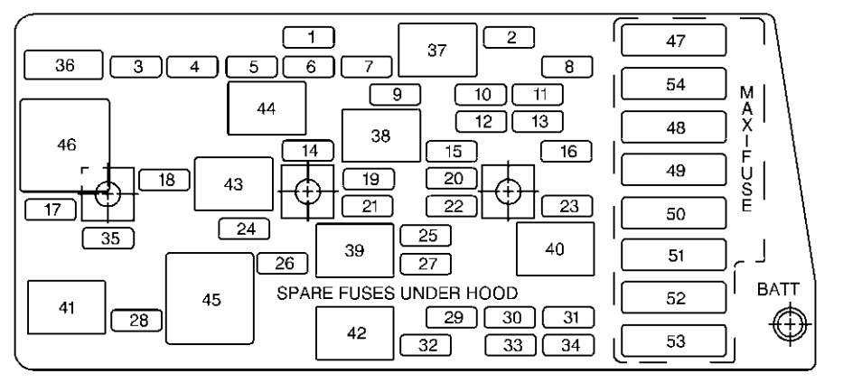
Engine compartment fuse block
There is one fuse block in the engine compartment located on the passenger’s side of the vehicle in front of the battery.
| Mini fuse | Usage |
| 1 | Rear Fog Lamp |
| 2 | Approach |
| 3 | Right Headlamp Motor |
| 4 | Left Headlamp Motor |
| 5 | Anti-Lock Brakes, Selective Ride Control |
| 6 | Fog Lamp |
| 7 | Blank |
| 8 | Headlamp Low Beam Right |
| 9 | Headlamp High Beam Right |
| 10 | Headlamp Low Beam Left |
| 11 | Horn |
| 12 | Headlamp High Beam Left |
| 13 | Fuel Pump |
| 14 | Cooling Fan – Ignition 3 |
| 15 | Oxygen Sensor |
| 16 | Powertrain Control Module |
| 17 | Throttle Control |
| 18 | Injector 2 |
| 19 | Engine Ignition |
| 20 | Blank |
| 21 | Blank |
| 22 | Injector 1 |
| 23 | Powertrain Control Module |
| 24 | Air Conditioning |
| 25 | Blank |
| 26 | Blank |
| 27 | Spare |
| 28 | Spare |
| 29 | Spare |
| 30 | Spare |
| 31 | Spare |
| 32 | Spare |
| 46 | Cooling Fan 2 |
| 47 | Blank |
| 48 | Blank |
| 49 | Cooling Fan 1 |
| 50 | Air Pump |
| 51 | Selective Ride Control |
| 52 | Anti-lock breakes |
| 53 | Anti-lock brakes electronics |
| 54 | Fuse puller |
| Relay | Usage |
| 33 | Air Pump |
| 34 | Air Conditioner and Clutch |
| 35 | Fuel Pump |
| 36 | Horn |
| 37 | Rear Fog Lamp |
| 38 | Back-Up Lamps |
| 39 | Fog Lamp |
| 40 | Blank |
| 41 | Blank |
| 42 | Ignition 2 |
| 43 | Cooling fan 2 |
| 44 | Cooling fan 3 |
| 45 | Cooling fan 1 |
WARNING: Terminal and harness assignments for individual connectors will vary depending on vehicle equipment level, model, and market.