
Year of production: 2017, 2018
Engine Compartment Fuse Block
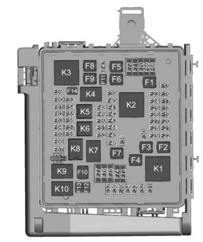
| Fuses | Usage |
| F1 | ABS pump |
| F2 | — |
| F3 | Driver power seat |
| F4 | Cooling fan |
| F5 | Passenger power seat |
| F6 | — |
| F7 | — |
| F8 | — |
| F9 | — |
| F10 | — |
| F11 | — |
| F12 | Front wiper |
| F13 | Starter |
| F14 | Brake vacuum pump |
| F15 | — |
| F16 | Heated seat |
| F17 | Passenger window |
| F18 | Body control module 4 |
| F19 | Airbag module/AOS |
| F20 | OnStar/Navigation (if equipped) |
| F21 | Body control module 6 |
| F22 | ABS valve |
| F23 | — |
| F24 | — |
| F25 | Steering column lock |
| F26 | Body control module 2 |
| F27 | — |
| F28 | Body control module 3 |
| F29 | Body control module 8 |
| F30 | Windshield wiper |
| F31 | Right HID headlamp |
| F32 | Left HID headlamp |
| F33 | — |
| F34 | Horn |
| F35 | — |
| F36 | Left high-beam headlamp |
| F37 | Right high-beam headlamp |
| F38 | Headlamp leveling |
| F39 | — |
| F40 | Rear electrical center/Ignition |
| F41 | Malfunction indicator lamp/Ignition |
| F42 | Instrument panel body/Ignition |
| F43 | Exhaust valve/Active fuel management |
| F44 | AOS display/Ignition |
| F45 | Sunroof |
| F46 | Body control module 7 |
| F47 | CGM |
| F48 | — |
| F49 | Heated steering whee |
| F50 | Fuel system control module/Ignition |
| F51 | Exhaust valve |
| F52 | A/C clutch |
| F53 | — |
| F54 | Coolant pump |
| F55 | — |
| F56 | — |
| F57 | Engine control module/Ignition |
| F58 | Transmission control module/Ignition |
| F59 | — |
| F60 | Transmission control module battery |
| F61 | MAF/O2 sensor |
| F62 | Ignition coils – odd |
| F63 | Non-walk/O2 sensor |
| F64 | Ignition coils – even |
| F65 | — |
| F66 | Engine control module 1 |
| F67 | Engine control module 2 |
| F68 | — |
| F69 | — |
| F70 | — |
| F71 | — |
| F72 | — |
| F73 | — |
| F74 | — |
| F75 | — |
| F76 | — |
| F77 | — |
| Relays | Usage |
| K1 | — |
| K2 | Run/Crank |
| K3 | — |
| K4 | Vacuum pump |
| K5 | — |
| K6 | Coolant pump |
| K7 | Engine control module |
| K8 | A/C control |
| K9 | — |
| K10 | Starter |
Rear Compartment Fuse Block
The rear compartment fuse block is on the right side under the trunk load floor.

| Fuses | Usage |
| F1 | Rear defogger |
| F2 | Front HVAC |
| F3 | Electric parking brake |
| F4 | — |
| F5 | — |
| F6 | Rear drive control module |
| F7 | Right window 1 |
| F8 | — |
| F9 | Left window 1 |
| F10 | Heated mirror 1 |
| F11 | — |
| F12 | Heated steering wheel |
| F13 | — |
| F14 | HVAC control |
| F15 | — |
| F16 | Display |
| F17 | Camera |
| F18 | — |
| F19 | Front ventilated seat 1 |
| F20 | Reverse lamps |
| F21 | — |
| F22 | — |
| F23 | Body control module 1 |
| F24 | — |
| F25 | — |
| F26 | — |
| F27 | RGB lights |
| F28 | Passive entry/Passive start battery 1 |
| F29 | Data link connector |
| F30 | Canister vent |
| F31 | Memory seat module folding top |
| F32 | Memory seat module |
| F33 | Wireless charger |
| F34 | Engine control module battery |
| F35 | Fuel pump/Fuel system control module |
| F36 | — |
| F37 | Electric steering column lock |
| F38 | Mirror window module |
| F39 | Rear closure |
| F40 | — |
| F41 | Battery regulated voltage control |
| F42 | SADS |
| F43 | — |
| F44 | Folding top solenoid |
| F45 | Amplifier |
| F46 | FPPM 22 |
| F47 | Shunt |
| F48 | — |
| F49 | Steering wheel |
| F50 | Interior rearview mirror |
| F51 | Camera module |
| F52 | Rear parking assist |
| F53 | Electronic limited-slip differential (if equipped) |
| F54 | Side blind zone alert |
| F55 | Radio controls |
| F56 | Theft deterrent/Universal remote system (if equipped) |
| F57 | — |
| Relays | Usage |
| K1 | Rear defogger |
| K2 | Fuel pump |
| Circuit Breaker | Usage |
| CB1 | — |
| CB2 | Retained accessory power |
| CB3 | — |
WARNING: Terminal and harness assignments for individual connectors will vary depending on vehicle equipment level, model, and market.