Year of production: 1993
Main Fuse Block
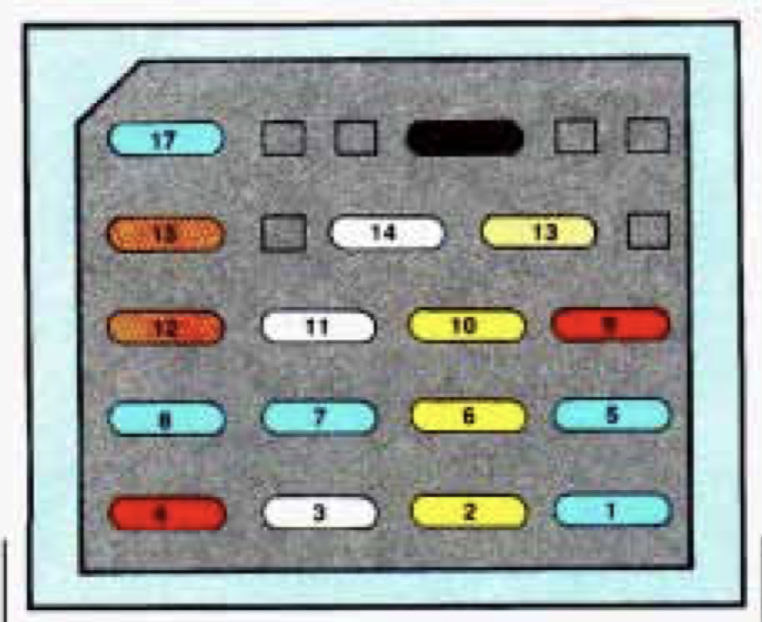
| Fuses/Circuit Breaker | Ampere rating [A] | Usage |
| 1 | 15 |
Air Bag: SIR Components |
| 2 | 20 |
Backup Lights; Daytime Running Lights Module (Canada); Turn Flasher |
| 3 | 25 |
HVAC Selector Switch(Heater/Air Conditioner); Rear Defogger |
| 4 | 10 |
Engine Control Module; Instrument Cluster; PASS-Key I P Decoder Module |
| 5 | 15 |
Engine Control Module; PASS-Key II@ Decoder Module; Fuel Pump Relay |
| 6 | 20 |
Brake LighVCruise Release Switch, Hazard Flasher |
| 7 | 15 |
Power Door Locks; Power Mirrors; Hatch Release |
| 8 | 15 |
Audio Alarm Module; Base@ Relay; Courtesy Lights: Console Compartment, Glove Box, Dome, Rearview Mirror and Radio |
| 9 | 10 |
Audio Alarm Module; Daytime Running Lights Module (Canada); Diagnostic Energy Reserve Module; Instrument Cluste |
| 10 | 20 |
Exterior Lighting |
| 11 | 20 | Cigarette Lighter; Horn Relay |
| 12 | 35 Circuit Breaker |
(35 Amp. Circuit Breaker) |
| 13 | 5 |
Brightness Control |
| 14 | 25 |
Windshield Wipermasher |
| 15 | 35 Circuit Breaker |
Power Windows |
| 16 | 3 |
Diagnostic Energy Reserve Module |
| 17 | 15 |
Radio |
Underhood Electrical Center
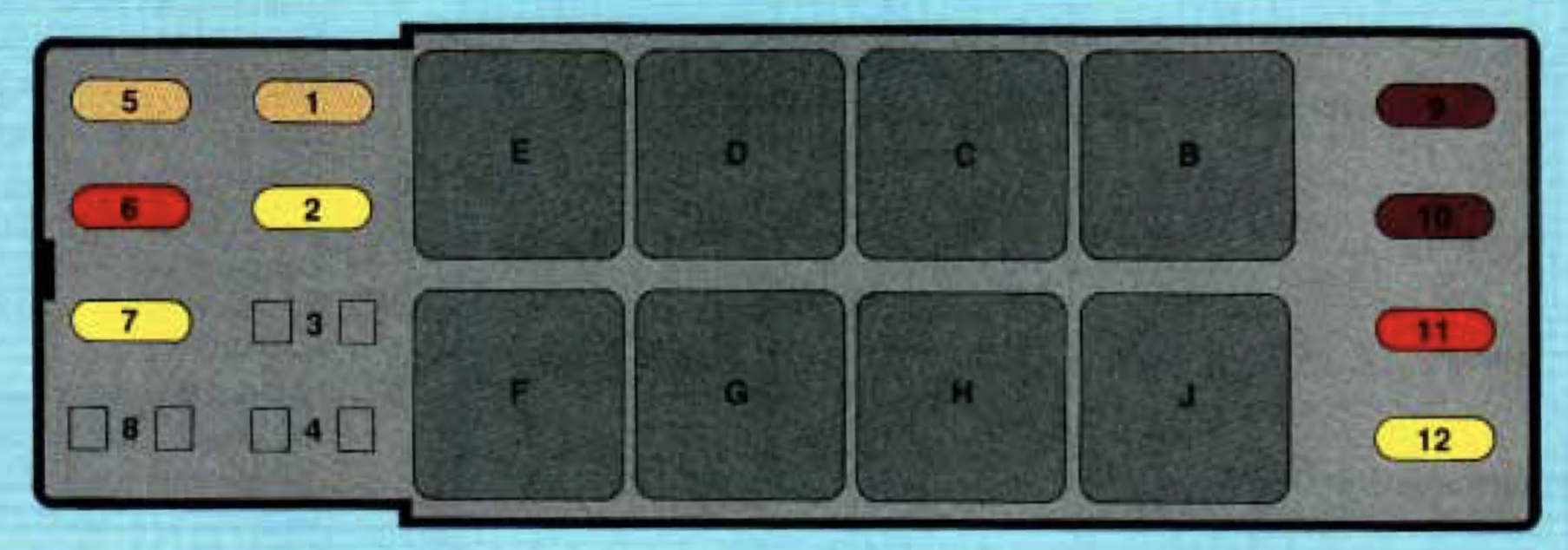
| Fuse | Ampere rating [A] | Usage |
| 1 | 5 |
Electronic Brake Control Module |
| 2 | 20 | Fog lamps |
| 3 | — | — |
| 4 | — | — |
| 5 | 5 |
Anti-Lock Brake Syste |
| 6 | 10 |
Coolant Fan Relays;EVAP Canister Purge Solenoid; Exhaust Gas Recirculation; LowCoolant Relay; Reverse Lockout Solenoid |
| 7 | 20 |
Air Injection Pump Assembly; Air Pump Relay |
| 8 | — | — |
| 9 | 7,5 |
Fuel Injector |
| 10 | 7,5 |
Fuel Injector |
| 11 | 10 |
VIN Engine Code S: Camshaft Position Sensor; Crankshaft Position Sensor; Electronic Ignition Module (10 Amp.) VIN Engine Code P: Ignition Coil; Ignition Coil Driver |
| 12 | 20 |
Air Conditioning Compressor Relay; Cruise Control Switches and Modul |
| Relays | Usage |
| A |
Air Conditioning Compresso |
| C |
Anti-Lock Brake System |
| D |
Primary Coolant Fan(Driver Side) |
| E |
Air Pump |
| F |
Secondary Coolant Fan (Passenger Side) |
| G |
Low Coolant |
| H |
Fan Lamps |
| J |
High Blower |