
Mercury Mountaineer Third Generation (2005 – 2010) – fuse box diagram
Year of production: 2005, 2006, 2007, 2008, 2009, 2010
Passenger compartment fuse panel
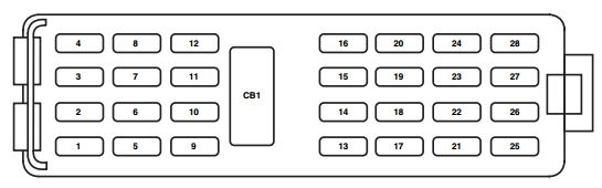
The fuse panel is located below the instrument panel on the driver’s side.
| Fuse/relay | Ampere rating [A] | Description |
| 1 | 20 | Moonroof, Adjustable pedals, DSM, Memory lumbar motor |
| 2 | 5 | Microcontroller power (SJB) |
| 3 | 20 | Radio |
| 4 | 20 | OBD II connector |
| 5 | 5 | Moonroof |
| 6 | 20 | Liftglass release motor, Door unlock/lock |
| 7 | 15 | Trailer stop/turn |
| 8 | 15 | Ignition switch power, PATS |
| 9 | 2 | 6R TCM/PCM (Ignition RUN/START), Fuel pump relay |
| 10 | 5 | Front wiper RUN/ACC relay in PDB |
| 11 | 5 | Radio start |
| 12 | 5 | Rear wiper motor RUN/ACC, Trailer battery charge relay in PDB, Radio |
| 13 | 15 | Heated mirror, Manual climate rear defrost indicator |
| 14 | 20 | Horn |
| 15 | 10 | Reverse lamps |
| 16 | 10 | Trailer reverse lamps |
| 17 | 10 | RCM, PAD lamp, OCS module |
| 18 | 10 | Reverse park aid, IVD switch, IVD, AWD module, Heated seat switches, Compass, Electrochromatic mirror, AUX climate control |
| 19 | — | Not used |
| 20 | 10 | Manual climate, DEATC, Brake shift |
| 21 | — | Not used |
| 22 | 15 | Brake switch, Bi-color stop lamps, CHMSL, All turn lamps |
| 23 | 15 | Interior lamps, Puddle lamps, Battery saver, Instrument illumination, Homelink |
| 24 | 10 | Cluster, Theft LED |
| 25 | 15 | Trailer park, Trailer electronic brake module |
| 26 | 15 | License plate/rear park lamp, Front park lamps, Manual climate |
| 27 | 15 | Tri-color stop lamps |
| 28 | 10 | Manual/DEATC |
| CB1 | 25 | Windows |
| Relay | Description |
| Relay 1 | Delayed ACC |
| Relay 2 | Rear defrost |
| Relay 3 | Park lamps |
| Relay 4 | RUN/START |
Power distribution box
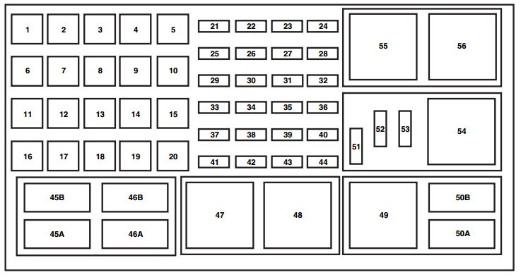
The power distribution box is located in the engine compartment. The power distribution box contains high-current fuses that protect your vehicle’s main electrical systems from overloads.
| Fuse/relay | Ampere rating [A] | Description |
| 1 | 50** | BATT 2 (SJB) |
| 2 | 50** | BATT 3 (SJB) |
| 3 | 50** | BATT 1 (SJB) |
| 4 | 30** | Fuel pump, Injectors |
| 5 | 30** | Third row seat (left) |
| 6 | 40** | IVD module |
| 7 | 40** | Powertrain Control Module (PCM) |
| 8 | 40** | Heated windshield (left) |
| 9 | 40** | Heated windshield (right) |
| 10 | 30** | Power seat (right) |
| 11 | 30** | Starter |
| 12 | 30** | Third row seat (right) |
| 13 | 30** | Trailer tow battery charger |
| 14 | 30** | Memory seats (DSM) |
| 40** | Non-memory seats | |
| 15 | 40** | Rear defrost, Heated mirrors |
| 16 | 40** | Blower motor |
| 17 | 30** | Trailer electronic brakes |
| 18 | 30** | Auxiliary blower motor |
| 19 | 30** | Running boards |
| 20 | — | Not used |
| 21 | 20* | Rear power point |
| 22 | 20* | Subwoofer |
| 23 | — | Not used |
| 24 | 10* | Powertrain Control Module (PCM) KAP, CAN vent |
| 25 | 20* | Front power point/Cigar lighter |
| 26 | 20* | AWD module |
| 27 | 20* | 6R Transmission module |
| 28 | 20* | Heated seats, Power mirrors |
| 29 | 20* | Headlamps (right) |
| 30 | 25* | Rear wiper |
| 31 | 15* | Fog lamps |
| 32 | 5* | Power mirrors |
| 33 | 30* | IVD module |
| 34 | 20* | Headlamps (left) |
| 35 | 10* | AC clutch |
| 36 | — | Not used |
| 37 | 30* | Front wiper |
| 38 | 15* | 5R Transmission |
| 39 | 15* | PCM power |
| 40 | 15* | Fan clutch, PCV valve, AC clutch relay, GCC fan |
| 41 | 15* | SDARS/DVD |
| 42 | 15* | Redundant brake switch, EVMV, MAFS, HEGO, EVR, VCT1, VCT2, CMCV, CMS |
| 43 | 15* | Coil on plug (4.6L engine only), Coil tower (4.0L engine only) |
| 44 | 15 | Injectors |
| 45A | — | Not used |
| 45B | — | GCC fan relay |
| 46A | — | Not used |
| 46B | — | Not used |
| 47 | — | Front wiper relay |
| 48 | — | PCM relay |
| 49 | — | Fuel pump relay |
| 50A | — | Fog lamps relay |
| 50B | — | AC clutch relay |
| 51 | — | Not used |
| 52 | — | A/C clutch (diode) |
| 53 | — | Not used |
| 54 | — | Trailer battery charger relay |
| 55 | — | Starter relay |
| 56 | — | Blower relay |
| * Mini Fuses ** Cartridge Fuses | ||
WARNING: Terminal and harness assignments for individual connectors will vary depending on vehicle equipment level, model, and market