
Lincoln Town Car mk3 (1998 – 2011) 3rd Generation – fuse box diagram
Year of production: 1998, 1999, 2000, 2001, 2002, 2003, 2004, 2005, 2006, 2007, 2008, 2009, 2010, 2011
Passenger compartment fuse panel
The fuse panel is located below and to the left of the steering wheel by the brake pedal.
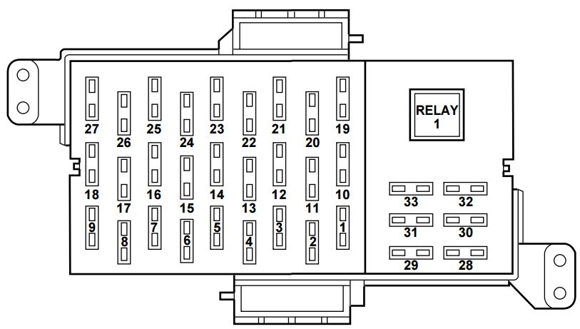
| Fuse/relay location | Ampere rating [A] | Description |
| 1 | 10 | Lighting Control Module (LCM), Left-Hand Low Beam Headlamp |
| 2 | 30 | EATC Blower Motor |
| 3 | 10 | Lighting Control Module (LCM), Right-Hand Low Beam Headlamp |
| 4 | 7,5 | Instrument Cluster |
| 5 | 7,5 | Lighting Control Module (LCM), Park/Tail Lamps |
| 6 | 15 | EATC, Heated Seats |
| 7 | 15 | Lighting Control Module (LCM), Day/Night Sensor/Amplifier |
| 8 | 10 | Shift Lock, Speed Control, Air Suspension, Steering Wheel Rotation Sensor |
| 9 | 20 | Lighting Control Module (LCM), Multi-Function Switch, Hi Beam Headlamps |
| 10 | 20 | Brake Pedal Position (BPP) Switch, Brake Pressure Switch, Stop Lamps |
| 11 | 10 | Electronic Crash Sensor (Airbag) |
| 12 | 15 | Instrument Cluster, Anti-Theft, Ignition Switch, Ignition Coils |
| 13 | 10 | Anti-Lock Brake Module, Traction Control Switch |
| 14 | 7,5 | Transmission Control Switch, Lighting Control Module (LCM) |
| 15 | 20 | Multi-Function Switch, Turn Signals |
| 16 | 30 | Wiper Control Module (WCM), Windshield Wiper Motor |
| 17 | 10 | Digital Transmission Range (DTR) Sensor, Back-Up Lamps, EC Mirrors |
| 18 | 7,5 | Lighting Control Module (LCM), Front Radio Control Unit, Cellular Telephone Transceiver, Electronic Day/Night Mirror, Compass Module |
| 19 | 10 | EATC, Clock, Instrument Cluster, PCM |
| 20 | 7,5 | Lighting Control Module (LCM), ABS, Shift Lock |
| 21 | 20 | Multi-Function Switch, Hazard Lamps |
| 22 | 20 | Multi-Function Switch, High Mounted Stop Lamps |
| 23 | 20 | Datalink Connector, I/P Cigar Lighter |
| 24 | 5 | Front Radio Control Unit |
| 25 | 15 | Lighting Control Module (LCM), Courtesy/Demand Lamps |
| 26 | 5 | Digital Transmission Range (DTR) Sensor, Starter Relay Coil |
| 27 | 20 | Fuel Filler Door Release Switch |
| 28 | 10 | Heated Mirrors |
| 29 | 20 | LF Door Module, Door Locks, Decklid Release |
| 30 | 7,5 | LF Seat Module, Trunk Lid Release Switch, Door Lock Switches, LF Seat Control Switch, LF Door Module, Power Mirror Switch |
| 31 | 7,5 | Main Light Switch, Lighting Control Module (LCM) |
| 33 | 15 | Front Radio Control Unit, Digital Compact Disk Changer, Cellular Telephone Transceiver |
| Relay 1 | — | Accessory Delay Relay (Signature/Cartier) or Power Window Relay (Executive) |
Power distribution box
The power distribution box is located in the engine compartment.
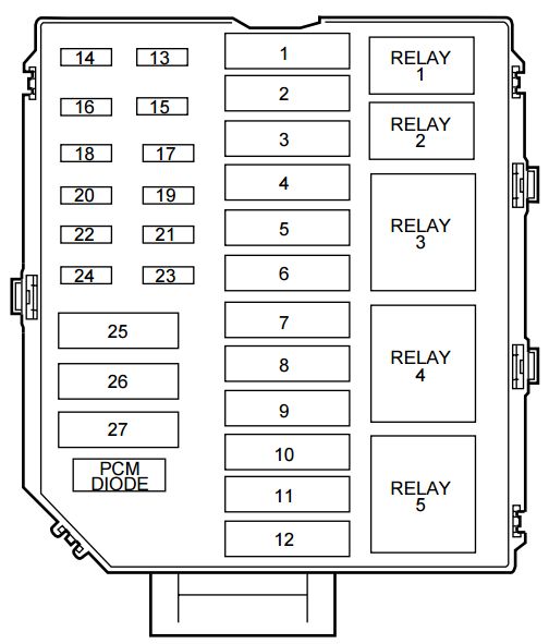
| Fuse/relay location | Ampere rating [A] | Description |
| 1 | 50** | Ignition Switch |
| 2 | 40** | Ignition Switch |
| 3 | 50** | Cooling Fan-High Speed |
| 4 | 30** | PCM Power Relay |
| 5 | 40** | I/P Fuse Panel, Fuses 10, 19, 21, 23, 25, 27 |
| 6 | 30** | Starting System |
| 7 | 50** | I/P Fuse Panel, Fuses 1, 3, 5, 7, 9, 31 |
| 8 | 30** | Driver Power Seat, I/P Fuse Panel, Fuse 30 |
| 9 | 50** | Anti-Lock Brakes |
| 10 | 40** | Rear Defrost |
| 11 | 40** | Accessory Delay Relay (Signature/Cartier), Power Window Relay (Executive), I/P Fuse Panel, Fuse 29 |
| 12 | 30** | Air Suspension |
| 13 | 15* | Charging System |
| 14 | 20* | Fuel Pump |
| 15 | — | Not used |
| 16 | 30* | Heated Seats |
| 17 | 10* | Air Suspension |
| 18 | 15* | Horn |
| 19 | 30* | Subwoofer, I/P Fuse Panel, Fuse 33 |
| 20 | 15* | Fuel Injectors |
| 21 | 15* | Heated Oxygen Sensors, Transmission Solenoids, EVAP Canaster Vent Solenoid, EGR Vacuum Regulator, EVAP Vapor Management Valve |
| 22 | — | Not Used |
| 23 | — | Not Used |
| 24 | 20* | Auxiliary Power Outlet |
| 25 | 30** | Power Lumbar, Passenger Power Seat |
| 26 | 30 CB | Cooling Fan-Low Speed |
| 27 | — | Not Used |
| Relay 1 | — | Fuel Pump Relay |
| Relay 2 | — | A/C Clutch Relay |
| Relay 3 | — | PCM Power Relay |
| Relay 4 | — | Air Suspension Relay |
| Relay 5 | — | Rear Defrost Relay |
| * Mini Fuses
** Maxi Fuses |
||
WARNING: Terminal and harness assignments for individual connectors will vary depending on vehicle equipment level, model, and market.