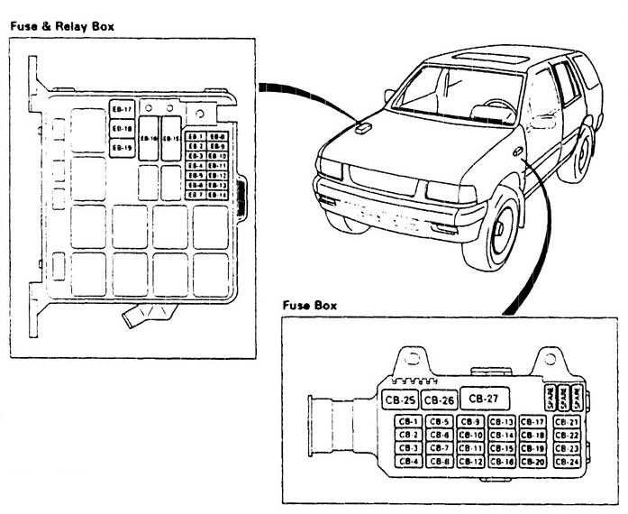
Isuzu Rodeo (1996) – fuse box diagram
Year of production: 1996
Fuse box diagram
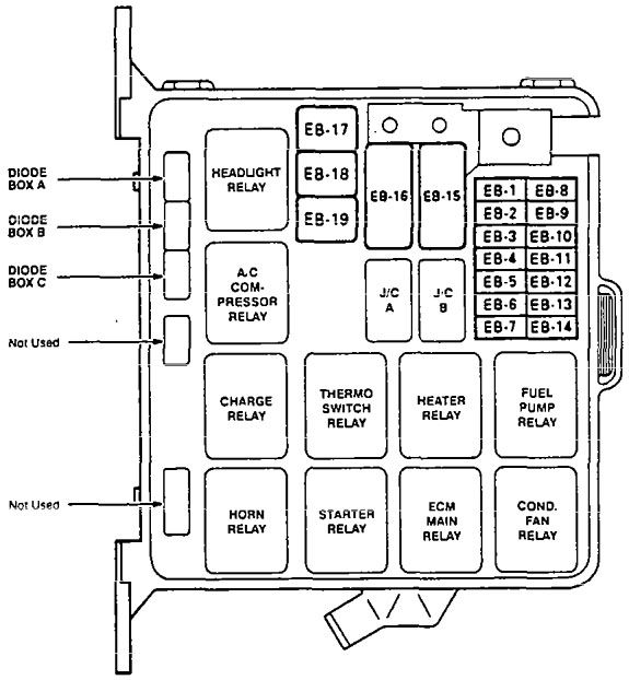
| Number | Fuse name | A | Function |
| EB-1 | HAZARD | 15 | Hazard warning light, flasher unit |
| EB-2 | HORN | 10 | Horn |
| EB-3 | — | — | — |
| EB-4 | BLOWER | 20 | Blower motor |
| EB-5 | AIR CON. | 10 | Compressor control |
| EB-6 | — | — | — |
| EB-7 | — | — | — |
| EB-8 | H/LAMP -LH | 10 | Left headlight, high beam indicator light |
| EB-9 | H/LAMP -RH | 10 | Right headlight |
| EB-10 | O2 SENSOR | 10 (L4) | Oxygen sensor |
| 20 (V6) | |||
| EB-11 | FUEL PUMP | 20 | Engine control |
| EB-12 | ECM | 15 | Engine control |
| EB-13 | (ABS) | 15 | (ABS) |
| EB-14 | (ABS H/U) | 15 | (ABS H/U) |
| EB-15 | IGN | 60 | Engine control |
| EB-16 | MAIN | 100 | Power distribution |
| EB-17 | ABS | 40 | ABS |
| EB-18 | — | — | — |
| EB-19 | COND. FAN | 30 | Cond fan |
| Diode | Usage |
| Diode Box A | Hatch gate, charge warning light (2.6l), staner relay (3 .2L) |
| Diode Box B | ECM relay (2.6L) |
| Diode Box C | Fuel pump relay (2.6l) |
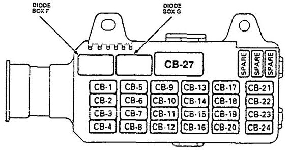
| Number | Fuse name | A | Function |
| CB-1 | STARTER | 10 | Starting system |
| CB-2 | — | — | — |
| CB-3 | ENGINE DEVICE | 15 | Charging system, engine control, A/T shift indicator |
| CB-4 | IG COIL | 15 | lgnition system |
| CB-5 | TAIL-ILLUMI | 15 | Taillights |
| CB-6 | — | — | — |
| CB-7 | METER | 15 | Gauges, indicators. vehicle speed sensor, seat belt warning, interlock system |
| CB-8 | — | — | — |
| CB-9 | ROOM | 10 | Dome, luggage room, courtesy and spot lights, sound system |
| CB-10 | — | — | — |
| CB-11 | FRONT WIPER | 20 | Wiper/Washer |
| CB-12 | ELEC. IG | 10 | Cruise control |
| CB-13 | STOP | 15 | Brake lights, automatic transmission control, rear wheel anti-lock brake system, crusie control |
| CB-14 | (DOOR LOCK) | 20 | Power windows |
| CB-15 | BACK UP, TURN | 15 | Back up lights, hazard warning lights, power windows, mirror defoggers |
| CB-16 | (REAR WIPER) | 10 | Rear wiper/washer |
| CB-17 | RR DEF NO.1 | 15 | Rear defoggef, hatch gate glass release |
| CB-18 | RR DEF NO.2 | 15 | Hatch gate glass release |
| CB-19 | AUDIO | 15 | Sound system |
| CB-20 | CIGAR | 15 | Cigarette lighter |
| CB-21 | SRS NO.1 | 10 | Supplemental restraint system (SRS) |
| CB-22 | SRS NO.2 | 10 | Supplemental restraint system (SRS) |
| CB-23 | (RWAL) | 20 | Rear wheel anti-lock brake system |
| CB-24 | (ABS) | 10 | (ABS) |
| CB-27 | (POWER WINDOW) | 30 | (Power windows) |
| Diode | Usage |
| Diode Box F | Dome light |
| Diode Box G | Courtesy light |
() – if equipped
ECM – Engine Control Module
O2 – Oxygen
H/U – Hydraulic Unit
WARNING: Terminal and harness assignments for individual connectors will vary depending on vehicle equipment level, model, and market.