
Ford Ka (1996 – 2008) – fuse box diagram
Year of production:
Fuse box diagram
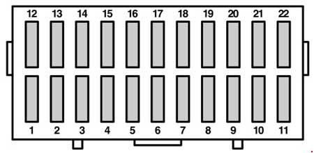
| Number | Ampers | Protected circuit |
| 1 | 20 | Heated rear window, central locking, heated exterior mirrors |
| 2 | 10 | Interior lamps, clock, radio, data link connector |
| 3 | 30 | ABS module |
| 4 | 3 | Engine control unit, main relay |
| 5 | 15 | Cigar lighter |
| 6 | 10 | Side lamps left-hand side, instrument panel illumination, lights on warning chime |
| 7 | 10 | Side lamps right-hand side, tail lamps |
| 8 | 10 | Dipped beam left-hand side |
| 9 | 10 | Dipped beam right-hand side |
| 10 | 10 | Main beam left-hand side, main beam indicator |
| 11 | 10 | Main beam right-hand side |
| 12 | 30 | Heater blower motor, recirculation motor |
| 13 | 15 | Lighting control, brake lamp |
| 14 | 30 | Electric windows |
| 15 | 20 | Lighting control |
| 16 | 20 | Wiper motor, washer pump motor |
| 17 | 15 | Air conditioning, ignition relay, instrument cluster, central locking, entry illumination |
| — | 7,5 | Ignition relay, instrument cluster, fuel pump relay, electronic engine management |
| 18 | 10 | Air bag module |
| 19 | 25 | Fuel pump, ignition transformer |
| 20 | 15 | Electronic engine management |
| — | 15 | Electronic engine management, ABS module, engine cooling fan relay |
| 21 | 10 | Rear fog lamp |
| — | 20 | Rear wiper motor, reversing lamp, air conditioning, heater water valve |
| 22 | 10 | Direction indicators |
WARNING: Terminal and harness assignments for individual connectors will vary depending on vehicle equipment level, model, and market.