Chrysler Aspen (2006 – 2009) – fuse box diagram
Year of production: 2006, 2007, 2008, 2009
Fuses (Interior)
The fuse block contains blade-type mini-fuses, relays, and circuit breakers for high-current circuits. It is located in the left kick panel. It is accessible through a snap-in cover.
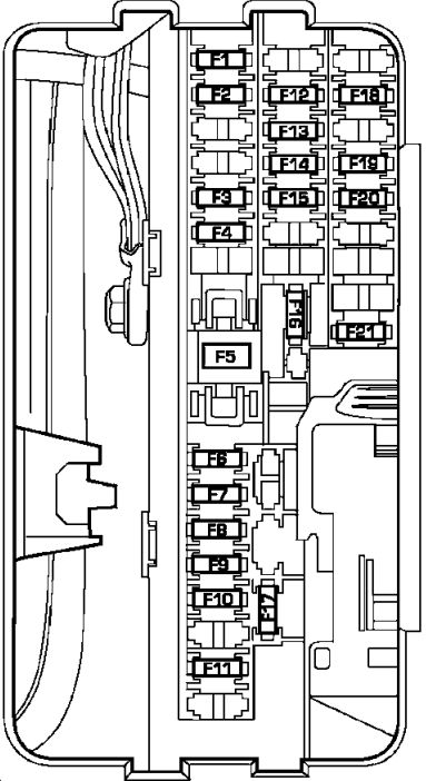
| Cavity | Mini fuse/color | Description |
| F1 | 15 Amp Blue | Instrument Cluster Battery Feed |
| F2 | 10 Amp Red | Spare |
| F3 | 10 Amp Red | Ignition Run/Start for Next Generation Controller (NGC), Integrated Power Module (IPM), AC Relay and Fuel Pump Relay |
| F4 | 10 Amp Red | Door Node and NonMemory Power Mirror Switch Battery Feed |
| F5 | (2) 10 Amp Red | Airbags (2 Fuses in Yellow Holder) |
| F6 | 2 Amp Clear | Ignition Run/Start Unlock |
| F7 | 25 Amp Natural | Radio Battery Feed |
| F8 | 10 Amp Red | Ignition Run/Start for Cluster/Transfer Case/Seat Sw. Back lighting |
| F9 | 10 Amp Red | Satellite Digital Audio Receiver (SDAR)/ Digital Video Disc (DVD) Battery Feed |
| F10 | 10 Amp Red | Spare |
| F11 | 10 Amp Red | Heated Mirrors |
| F12 | 20 Amp Yellow | Cluster Battery Feed |
| F13 | 10 Amp Red | Ignition Run HVAC Module/Heated Rear Glass (EBL) Relay |
| F14 | 10 Amp Red | ABS Module Ignition Run |
| F15 | 15 Amp Blue | Battery Feed Blue Tooth, Compass/Trip Computer (CMTC), Sentry Key Diagnostics |
| F16 | 20 Amp Yellow | Reconfigurable Power Outlets |
| F17 | 20 Amp Yellow | Ignition Run / Rear Park Assist / Second Row Heated Seats |
| F18 | 20 Amp Yellow | Cigar Lighter Ignition |
| F19 | 10 Amp Red | Spare Fuse |
| F20 | 15 Amp Blue | Heating & Air Conditioning w/ATC Only Battery Feed |
| F21 | 25 Amp Natural | Amplifier Battery Feed |
Fuses (Power Distribution Center)
Power distribution center located in the left side of the engine compartment.
| Cavity | Cartidge/fuse relay | Mini fuse | Description |
| 1 | 30 | — | Starter |
| 2 | 30 | — | Front Wiper |
| 3 | 40 | — | Brake Batt |
| 4 | 30 | — | JB Feed Acc # 2 |
| 5 | 40 | — | Power Seats |
| 6 | 30 | — | Run Remote Relay Feed |
| 7 | 40 | — | Blower Motor Relay Feed |
| 8 | 40 | — | JB Feed Acc Delay |
| 9 | Spare | — | Spare |
| 10 | 30 | — | ASD |
| 11 | 40 | — | Power Liftgate ( If Equipped) |
| 12 | 40 | — | JB Feed / Heated Rear Glass (EBL)/ T Case Brake |
| 13 | 30 | — | JB Feed RR |
| 14 | 40 | — | ESP Pump |
| 15 | 50 | — | JB Feed |
| 16 | — | 10 | Spare |
| 17 | — | Spare | Spare |
| 18 | — | 20 | Fuel Pump |
| 19 | — | 20 | Next Generation Controller (NGC) |
| 20 | — | 25 | 115v Power Inverter |
| 21 | — | 20 | ABS Batt |
| 22 | — | 20 | Next Generation Controller (NGC) Batt |
| 23 | — | 20 | Trailer Tow |
| 24 | — | 15 | A/C Clutch |
| 25 | — | 15 | Stop Lamp Switch |
| 26 | — | Spare | Spare |
| 27 | — | 20 | Run/Start Relay Feed |
| 28 | — | Spare | Spare |
| 29 | Relay | — | Run Start |
| 30 | Relay | — | Run Remote |
| 31 | Spare | — | — |
| 32 | Relay | — | Starter |
| 33 | Relay | — | Electronic Automatic Transaxle (EATX) |
| 34 | Relay | — | AC Clutch |
| 35 | Relay | — | Fuel Pump Rly |
| 36 | Spare | — | Spare |
| 37 | Relay | — | Stop Lamp Switch |
| 38 | Spare | — | Spare |
| 39 | Relay | — | Blower Motor |
| 40 | Relay | — | Auto Shut Down (ASD) Rly |
Fuses (Integrated Power Module)
Integrated Power Module is located in the left side of the engine compartment.
| Cavity | Cartridge fuse/ relay | Mini fuse | Description |
| 1 | Relay | — | Wiper On/Off Rly |
| 2 | Relay | — | Wiper Hi/Lo Rly |
| 3 | Relay | — | Horn Rly |
| 4 | Relay | — | Rear Wiper Rly |
| 5 | Relay | — | Lt Trailer-Tow Stop/ Turn Rly |
| 6 | Relay | — | Rt Trailer-Tow Stop/ Turn Rly |
| 7 | Relay | — | Park Lamps Rly |
| 8 | — | 10 | Lt Park Lamps |
| 9 | — | 10 | Trailer-Tow Park Lamps |
| 10 | — | 10 | Rt Park Lamps |
| 11 | Relay | — | Radiator Fan Hi Rly |
| 12 | — | 20 | Front Control Module (FCM) Batt #4 |
| 13 | — | 20 | Front Control Module (FCM) Batt #2 |
| 14 | — | 20 | Adjustable Pedal |
| 15 | — | 20 | Ft Fog Lamps |
| 16 | — | 20 | Horn |
| 17 | — | 20 | Rear Wiper |
| 18 | — | 20 | Front Control Module (FCM) Batt #1 |
| 19 | — | 20 | Lt Trailer-Tow Stop/ Turn |
| 20 | — | 20 | Front Control Module (FCM) Batt #3 |
| 21 | — | 20 | Rt Trailer-Tow Stop/ Turn |
| 22 | 30 | — | Front Control Module (FCM) BATT # 5 |
| 23 | 40 | — | Radiator Fan |
| 24 | Relay | — | Radiator Fan Lo Rly |
| 25 | Relay | — | Ft Fog Lamps Rly |
| 26 | Relay | — | Adjustable Pedal Rly |
| 27 | — | 30 | Ignition Off Draw (IOD) #1 |
| 28 | — | 30 | Ignition Off Draw (IOD) #2 |
| 29 | — | — | Spare |
| 30 | — | — | Spare |
WARNING: Terminal and harness assignments for individual connectors will vary depending on vehicle equipment level, model, and market.