
Freightliner BUSINESS CLASS M2 – fuse box diagram
Year of production:
Main Fuse Box
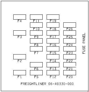
| Number | Function | Ampere ratting [A] |
| F1 | VCU (MBE900 only) | 10 |
| F2 | Blower Motor | 30 |
| F3 | Engine ECU | 20 |
| F4 | Transmission Control Unit | 30 |
| F5 | Ignition Switch | 5 |
| F6 | Spare | — |
| F7 | Bulkhead Module | 30 |
| F8 | ICU | 10 |
| F9 | Transmission Control Unit | 20 |
| F10 | Door Locks (optional) | 10 |
| F11 | Mirrors (optional) | 15 |
| F12 | Radio/Diagnostics | 20 |
| F13 | Chassis Module | 30 |
| F14 | L7H Power Windows (optional) | 15 |
| F15 | Bulkhead Module | 30 |
| F16 | ABS ECU | 15 |
| F17 | Chassis Module | 30 |
| F18 | Bulkhead Module | 30 |
| F19 | Chassis Module | 30 |
| F20 | Bulkhead Module | 30 |
| F21 | R/H Power Windows (optional) | 15 |
| F22 | Bulkhead Module | 30 |
| F23 | Spare | — |
| F24 | Spare | — |
| F25 | Spare | — |
| F26 | Spare | — |
| M1 | Battery Power | 125 |
| M2 | Battery Power | 125 |
| M3 | Battery Power | 150 |
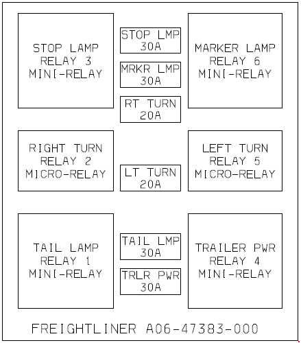
Trailer Fuse Box
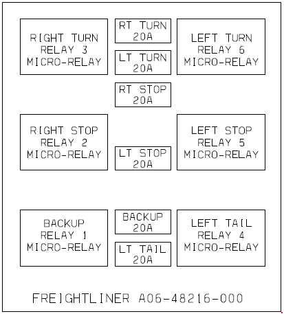
Taillight Fuse Box
WARNING: Terminal and harness assignments for individual connectors will vary depending on vehicle equipment level, model, and market.