Suzuki Baleno (2015 – 2018) – fuse box diagram
Year of production: 2015, 2016, 2017, 2018
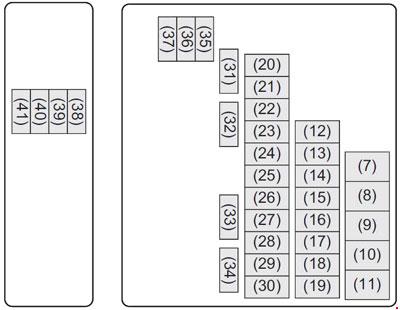
Fuse box in the engine compartment
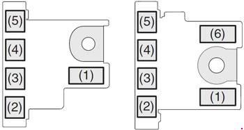
| No. |
A |
Function/component |
| 1 | 120 | FL1 |
| 2 | 100 | FL2 |
| 3 | 80 | FL3 |
| 4 | 100 | FL4 |
| 5 | 50 | FL5 |
| 6 | 150 | FL6 |
| 7 | 30 | Starting motor |
| 8 | 30 | Blower fan |
| 9 | 40 | Battery |
| 10 | 40 | ABS motor |
| 11 | 40 | Ignition switch |
| 12 | 30 | B/U |
| 13 | 30 | Sub battery |
| 14 | – | Not used |
| 15 | – | Not used |
| 16 | 25 | ABS control module |
| 17 | 15 | Headlight (Left) |
| 18 | 15 | Headlight (Right) |
| 19 | – | Not used |
| 20 | – | Not used |
| 21 | 30 | Radiator fan |
| 22 | 60 | Power steering |
| 23 | 5 | ECM |
| 24 | 20 | Fuel pump |
| 25 | 20 | Front fog light |
| 26 | 10 | Air compressor |
| 27 | 50 | Ignition switch 2 |
| 28 | 15 | Transaxle |
| 29 | 15 | FI (GAS |
| 30 | FI main (DIESEL) | |
| 30 | 15 | CVT pump |
| 31 | – | Not used |
| 32 | – | Not used |
| 33 | 5 | Starting Signal |
| 34 | – | Not used |
| 35 | 20 | INJ DRV (DIESEL) |
| 36 | – | Not used |
| 37 | 10 | FI (DIESEL) |
| 38 | – | Not used |
| 39 | 25 | Headlight high |
| 40 | 15 | Headlight high (Right) |
| 41 | 15 | Headlight high (Left) |
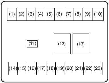
Fuse box under the dashboard
For vehicle without keyless push start system or keyless entry system
| No. |
A |
Function/component |
| 1 | 10 | Back-up light |
| 2 | 15 | Ignition coil |
| 3 | 10 | Meter |
| 4 | 10 | Wiper |
| 5 | 5 | Ignition-2 signal |
| 6 | 15 | Washer |
| 7 | 25 | Front wiper |
| 8 | 10 | Tail light |
| 9 | 10 | Hazard |
| 10 | 10 | Stop light |
| 11 | 30 | Power window |
| 12 | 15 | ACC-2 |
| 13 | 5 | ACC |
| 14 | 5 | Starting signal |
| 15 | 10 | Ignition-1 signal |
| 16 | 10 | Air bag |
| 17 | 5 | ABS control module (if equipped) |
| 18 | 15 | Horn |
| 19 | 20 | Door lock |
| 20 | 25 | Rear defogger |
| 21 | 15 | Radio |
| 22 | 5 | Dome light |
| 23 | 10 | Dome light-2 |
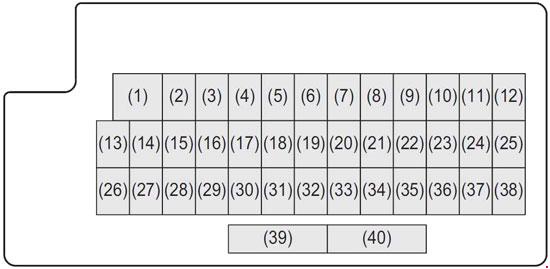
For vehicle with keyless push start system or keyless entry system
| No. |
A |
Function/component |
| 1 | 30 | Power window |
| 2 | 10 | Meter |
| 3 | 15 | Ignition coil |
| 4 | 5 | Ignition-1 signal 2 |
| 5 | – | Not used |
| 6 | – | Not used |
| 7 | – | Not used |
| 8 | 20 | Door lock |
| 9 | 15 | Steering lock |
| 10 | 10 | Hazard |
| 11 | 5 | A-STOP controller |
| 12 | 10 | RR fog lamp |
| 13 | 5 | ABS control module |
| 14 | 15 | Seat heater |
| 15 | 5 | Ignition-1 signal 3 |
| 16 | 10 | Dome light-2 |
| 17 | 5 | Dome light |
| 18 | 15 | Radio |
| 19 | 5 | CONT |
| 20 | 5 | Key 2 |
| 21 | 20 | Power window timer |
| 22 | 5 | Key |
| 23 | 15 | Horn |
| 24 | 5 | Tail light (Left) |
| 25 | 10 | Tail light |
| 26 | 10 | Air bag |
| 27 | 10 | Ignition-1 signal |
| 28 | 10 | Back-up light |
| 29 | 5 | ACC-3 |
| 30 | 20 | Rear defogger |
| 31 | 10 | Heated mirror |
| 32 | 15 | ACC-2 |
| 33 | 5 | ACC |
| 34 | 10 | Wiper |
| 35 | 5 | Ignition-2 signal |
| 36 | 15 | Washer |
| 37 | 25 | Front wiper |
| 38 | 10 | Stop light |
| 39 | – | Not used |
| 40 | 25 | Rear defogger 2 |
WARNING: Terminal and harness assignments for individual connectors will vary depending on vehicle equipment level, model, and market.