
Skoda Octavia (2012) – fuse box diagram
Year of production: 2012
Fuse box in engine compartment

| Number | Power consumer |
| F1 | Not assigned |
| F2 | Control unit for automatic gearbox DQ 200 |
| F3 | Measuring circuit |
| F4 | Valves for ABS |
| F5 | Control unit for automatic gearbox |
| F6 | Instrument cluster, windshield wiper lever and turn signal light lever |
| F7 | Power supply terminal 15, Starter |
| F8 | Radio |
| F9 | Not assigned |
| F10 | Engine control unit, Main relay |
| F11 | Control unit for auxiliary heating |
| F12 | Control unit for CAN databus |
| F13 | Engine control unit |
| F14 | Ignition |
| F15 | Lambda probe |
| Glow plug system relay | |
| F16 | Central control unit, right main headlight, right rear light unit |
| F17 | Horn |
| F18 | Amplifier for digital sound processor |
| F19 | Front window wiper |
| F20 | Water pump |
| Valve for fuel dosing | |
| F21 | Lambda probe |
| F22 | Clutch pedal switch, brake pedal switch |
| F23 | Secondary air pump |
| Air mass meter | |
| Fuel high pressure pump | |
| F24 | Activated charcoal filter, exhaust gas recirculation valve |
| F25 | Pump for ABS |
| F26 | Central control unit, left main headlight, left rear light unit |
| F27 | Secondary air pump |
| Glow plug system | |
| F28 | Not assigned |
| F29 | Power supply terminal 30 |
| F30 | Terminal Xa) |
| a) In order not to drain the battery unnecessarily when starting the engine, the electrical components of this terminal are automatically switched off. | |
Fuse box in dash panel
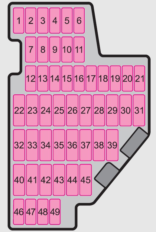
| Number | Power consumer |
| 1 | Diagnostic socket, Engine control unit, Electrical fuel pump |
| 2 | Control unit for ABS, ESP |
| 3 | Airbag |
| 4 | Heating, Air conditioning system, Reversing lights |
| 5 | Control unit for headlamp beam adjustment |
| 6 | Instrument cluster, Control unit for automatic gearbox, Control unit for electromechanical power steering, Parking aid; Haldex clutch |
| 7 | Not assigned |
| 8 | Not assigned |
| 9 | Not assigned |
| 10 | Not assigned |
| 11 | Not assigned |
| 12 | Central locking control unit |
| 13 | Diagnostic socket, Light switch |
| 14 | Control unit for automatic gearbox, Selector lever lock |
| 15 | Central control unit – interior lights |
| 16 | Climatronic |
| 17 | Not assigned |
| 18 | Rear window wiper |
| 19 | Control unit for trailer detection |
| 20 | Not assigned |
| 21 | Cornering lights for the left and right side |
| 22 | Air blower for Climatronic |
| 23 | Front power window |
| 24 | Cigarette lighter |
| 25 | Rear window heater |
| Rear window heater, Auxiliary heating (auxiliary heating and ventilation) | |
| 26 | Power socket in the luggage compartment |
| 27 | Fuel pump relay, Injection valves (diesel engine) |
| 28 | Radio |
| 29 | Engine control unit, Crankcase ventilation heater |
| 30 | Control unit for automatic gearbox |
| 31 | Vacuum pump |
| 32 | Rear power window |
| 33 | Electric sliding/tilting roof |
| 34 | Control unit for convenience functions |
| 35 | Anti-theft alarm system |
| 36 | Headlight cleaning system |
| 37 | Front seat heating |
| 38 | Heated rear seats |
| 39 | Instrument cluster, windshield wiper lever and turn signal light lever |
| 40 | Air blower for heating and air conditioning |
| 41 | Not assigned |
| 42 | Not assigned |
| 43 | Towing device |
| 44 | Towing device |
| 45 | Towing device |
| 46 | Seat heaters |
| 47 | Relay for auxiliary heating |
| 48 | Phone |
| 49 | Light switch |
WARNING: Terminal and harness assignments for individual connectors will vary depending on vehicle equipment level, model, and market.