MG GS – fuse box diagram
Years of production:
Battery fuse box
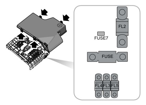
| No. | A | Protected components |
| FUSE | — | — |
| FUSE7 | 5 | Power management DC convertor |
| FL2 | 200 | Alternator |
| FL3 | 60 | Electronic power assisted steering |
| FL4 | 200 | Engine compartment fuse box |
| FL5 | 50 | Passenger compartment fuse bo |
Passenger Compartment Fuse Box
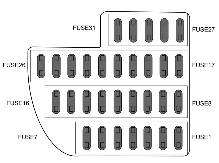
| No. | A | Protected components |
| FUSE1 | 15 | Rear accessories power socket |
| FUSE2 | — | — |
| FUSE3 | — | — |
| FUSE4 | — | — |
| FUSE5 | — | — |
| FUSE6 | 5 | Radio |
| FUSE7 | 15 | Front 12V power socket |
| FUSE8 | 25 | TCM(7AT) |
| FUSE9 | — | — |
| FUSE10 | 5 | Driver door switch pack |
| FUSE11 | 10 | Gateway |
| FUSE12 | 5 | Parking distance control unit,rain sensor |
| FUSE13 | 20 | Headlamp,dynamic headlamp leveling control module |
| FUSE14 | 2 | Ignition switch |
| FUSE15 | 5 | Immobiliser coil |
| FUSE16 | 10 | Diagnostic socket |
| FUSE17 | 5 | Slip control system |
| FUSE18 | 5 | Power management DC convertor |
| FUSE19 | 20 | Seat heater switch |
| FUSE20 | — | — |
| FUSE21 | 7,5 | PRND display,EPB Switch, exterior mirror adjustment, switch-stop/start system |
| FUSE22 | 10 | Supplemental restraint system |
| FUSE23 | — | — |
| FUSE24 | — | — |
| FUSE25 | 5 | Master light switch |
| FUSE26 | — | — |
| FUSE27 | — | — |
| FUSE28 | 5 | Instrument pack |
| FUSE29 | 10 | ATC controller/MTC controller |
| FUSE30 | 5 | A/C and ICE interface |
| FUSE31 | 15 | Radio/color radio/NAV |
Engine Compartment Fuse Box
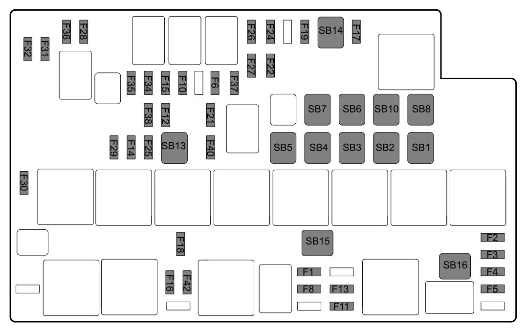
| No. | A | Protected components |
| F1 | 10 | Engine control module |
| F2 | 15 | Engine control module |
| F3 | 20 | Upstream oxygen sensor, downstream oxygen sensor, clutch bottom sensor, variable camshaft timing exhaust, variable camshaft timing intake, electronic thermostat |
| F4 | 15 | Heat air flow meter, ignition coil 1, 2, 3, 4 |
| F5 | 10 | Canister purge valve, wastegate control valve, dump valve, brake lamp switch sensor, oil control valve, neutral switch |
| F6 | 7,5 | Exterior mirror heater |
| F7 | — | — |
| F8 | 20 | Fuel pump relay |
| F9 | — | — |
| F10 | 30 | Driver door window lift motor |
| F11 | 5 | Supplemental restraint system |
| F12 | 25 | Body control module |
| F13 | 20 | Passenger power seat adjustment switch |
| F14 | 25 | Body control module |
| F15 | 30 | Front passenger door window lift switch |
| F16 | 10 | TCM(TST), engine control module, shift control module (TST) |
| F17 | 10 | Air condition compressor relay |
| F18 | 5 | Engine control module |
| F19 | 20 | Driver power seat adjustment switch |
| F20 | — | — |
| F21 | 10 | Ignition switch relay |
| F22 | 25 | Body control module |
| F23 | — | — |
| F24 | 5 | Transmission relay coil (TST) |
| F25 | 25 | Body control module |
| F26 | 30 | Rear left window lift switch |
| F27 | 30 | Rear right window lift switch |
| F28 | 20 | Horn relay |
| F29 | 25 | Front wiper relay |
| F30 | 20 | Front windscreen washer relay |
| F31 | 20 | Rear windscreen wiper relay |
| F32 | 20 | Rear windscreen washer relay |
| F33 | — | — |
| F34 | 10 | Front left headlamp |
| F35 | 10 | Front right headlamp |
| F36 | 30 | Headlamp washer relay |
| F37 | 15 | Front fog lamp relay |
| F38 | 25 | Body control module |
| F39 | — | — |
| F40 | 30 | Rear windscreen heater relay |
| F41 | — | — |
| F42 | 10 | Reverse lamp switch (6MT), body control module, instrument pack, MTC controller |
| SB1 | 30 | Main relay |
| SB2 | 60 | Cooling fan-high speed |
| SB3 | 50 | Cooling fan-middle speed |
| SB4 | 40 | KL.R power control relay |
| SB5 | 40 | Starter relay |
| SB6 | 30 | Slip control system-valve |
| SB7 | 40 | Slip control system-pump |
| SB8 | 40 | Blower relay |
| SB9 | — | — |
| SB10 | 25 | Body control module |
| SB11 | — | — |
| SB12 | — | — |
| SB13 | 40 | TCM(TST) |
| SB14 | 40 | Electrical park brake control module |
| SB15 | 40 | Power management DC convertor |
| SB16 | 40 | Cooling fan-low speed |
WARNING: Terminal and harness assignments for individual connectors will vary depending on vehicle equipment level, model, and market.