
Komatsu PC40-7 – fuse box diagram
Year of production:
Fuse box
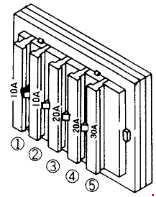
| Numbers | Ampers | Protected Circuit |
| 1 | 10 | Spare fuse |
| 2 | 10 | Engine control system, valve for work equipment lever lock |
| 3 | 20 | Monitor panel, wiper*, heater*, room lamp*, radio* |
| 4 | 20 | Head lamp, travel selector valve |
| 5 | 30 | Engine control system |
| * These items are only for the cab specification machine. | ||
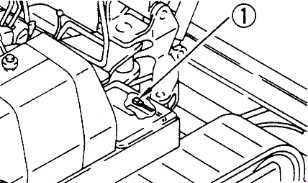
Fusible Link
If the power does not come on when the starting switch is turned to the ON position, the wire-shaped fusible link ® may be cut, so remove the cover on the right side of the chassis, and check or replace.
WARNING: Terminal and harness assignments for individual connectors will vary depending on vehicle equipment level, model, and market.