
KIA Cadenza (2017 – 2018) – fuse box diagram
Year of production: 2017, 2018
Instrument panel (Driver’s side fuse panel)
Inside the fuse/relay panel covers, you can find the fuse/relay label describing fuse/relay name and capacity.

| Fuse nume | Fuse rating [A] | Protected component |
| MODULE 7 | 10 | Driver Door Module, Passenger Door Module |
| SPARE | 10 | Spare |
| MODULE 3 | 10 | Stop Lamp Switch, BCM (Body Control Module), Sports Mode Switch |
| MODULE 5 | 10 | Console Switch, Blind Spot Detection Radar Left Handle side/Right Handle side, BCM (Body Control Module), Smart Cruise Control Unit, Crash Pad Switch, Fuel Filler & Trunk Open Switch, Lane Departure Warning Unit, Steering Tilt & Telescopic Module |
| IG1 | 25 | PCB (Printed Circuit Board) Block |
| MDPS | 7,5 | MDPS (Motor Driven Power Steering) Unit |
| MODULE 6 | 10 | Air Conditioner Switch, Air Conditioner Control Module, Electro Chromic Mirror, Head Lamp Left Handle side/Right Handle side, Auto Head Lamp Leveling Device Module, Front Seat Warmer Control Module, Front Air Ventilation Seat Control Module, Rear Seat Warmer Control Module, Audio/Video & Navigation Head Unit, Driver Integrated memory system Module, Auto Transmission Shift Lever Indicator, Multipurpose Check Connector |
| CLUSTER | 10 | Instrument Cluster, Head-Up Display |
| AIR BAG | 15 | SRS (Supplemental Restraint System) Control Module |
| MULTIMEDIA 1 | 20 | IGPM (Integrated Gateway Power control Module), Audio/Video & Navigation Head Unit |
| A/BAG IND | 7,5 | Air Conditioner Switch, Instrument Cluste |
| MODULE 4 | 10 | Smart Key Control Module, Immobilizer Module |
| SPARE 2 | 10 | Spare |
| A/CON | 7,5 | Air Conditioner Switch, Air Conditioner Control Module, Ionizer, Engine Room Junction Block (Blower Relay) |
| MEMORY 1 | 10 | Head-Up Display, Instrument Cluster, Wireless Charger Unit , Analog Clock, BCM (Body Control Module), Rain Sensor, Driver Door Module, Power Trunk Module, Passenger Door Module, Air Conditioner Switch, Air Conditioner Control Module, Security Indicator |
| MEMORY 2 | 15 | Driver Door Module |
| MEMORY 3 | 10 | Passenger Door Module |
| START | 7,5 | Transaxle Range Switch, ECM (Engine Control Module) |
| HEATED STEERING |
15 | BCM (Body Control Module) |
| MODULE 9 | 7,5 | Surround View Unit, Rear Seat Warmer Control Module, Front Seat Warmer Control Module, Front Air Ventilation Seat Control Module |
| WASHER | 15 | Multifunction Switch |
| INTERIOR LAMP |
10 | Glove Box Lamp, Passenger Foot Lamp, Driver Foot Lamp, Trunk Room Lamp, Front Vanity Lamp Switch Left Handle side/Right Handle side, Overhead Console Lamp, Room Lamp, Rear Personal Lamp Left Handle side/Right Handle side |
| DOOR LOCK | 20 | Door Lock/Unlock Relay |
| S/HEATER (FR) | 25 | Front Seat Warmer Control Module, Front Air Ventilation Seat Control Module |
| SMART KEY 2 | 10 | Start/Stop Button Switch |
| BRAKE SWITCH | 10 | Stop Lamp Switch, Immobilizer Module, Smart Key Control Module |
| AMP | 30 | AMP (Amplifier) |
| P/WINDOW (RH) | 25 | Passenger Safety Power Window Module, Rear Power Window Switch Right Handle side |
| SUNROOF 1 | 20 | Sunroof Control Unit (Glass) |
| TRUNK | 10 | Trunk Relay, Fuel Filler & Trunk Open Switch, Engine Room Junction Block(Fuel Lid Relay) |
| MULTIMEDIA 2 | 10 | Front Monitor |
| POWER TRUNK | 30 | Power Trunk Module |
| S/HEATER (RR) | 25 | Rear Seat Warmer Control Module |
| SPARE 1 | 10 | Spare |
| P/WINDOW (LH) | 25 | Rear Power Window Switch Left Handle side, Driver Safety Power Window Module |
| P/SEAT (PASS) | 30 | Passenger Seat Manual Switch |
| SUNROOF 2 | 20 | Sunroof Control Unit (Roller) |
| POWER HANDLE | 15 | Steering Tilt & Telescopic Module |
| B/ALARM HORN | 10 | Burglar Alarm Horn Relay |
| SMART KEY 1 | 15 | Smart Key Control Module |
| MODULE 1 | 7,5 | Data Link Connector, Hazard Switch, Console Switch |
| P/SEAT (DRV) | 30 | Driver Seat Manual Switch, Driver Integrated memory system Module |
| POWER OUTLET | 20 | Front Power Outlet, Rear Power Outlet |
| MODULE 2 | 10 | AMP (Amplifier), Surround View Unit, BCM (Body Control Module), Air Conditioner Control Module, Analog Clock, Wireless Charger Unit, Air Conditioner Switch, Smart Key Control Module, Front Monitor, Audio/Video & Navigation Head Unit, Engine Room Junction Block(Power Outlet Relay), USB Charger |
| SPARE | 10 | Spare |
| MODULE 8 | 7,5 | BCM (Body Control Module), Smart Key Control Module |
Engine compartment
Inside the fuse/relay panel covers, you can find the fuse/relay label describing fuse/relay name and capacity.
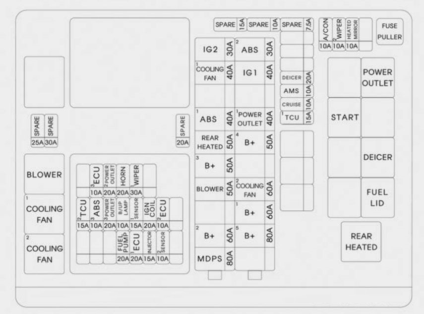
| Fuse rating [A] | Ampere rating [A] | Circuit protected | |
| MULTI FUSE | MDOS | 80 | MDPS (Motor Driven Power Steering) UNIT |
| B+2 | 60 | IGPM (Integrated Gateway Power control Module) | |
| BLOWER | 50 | Blower Relay | |
| B+3 | 50 | IGPM (Integrated Gateway Power control Module) | |
| REAR HEATED | 50 | Rear Heated Relay | |
| ABS1 | 40 | ESC (Electronic Stability Control) Module | |
| IG2 | 30 | Without Smart Key : Start Relay, Ignition Switch With Smart Key : Start Relay |
|
| B+5 | 80 | WIPER1, HORN, ECU2, FUEL PUMP, Engine Control Relay | |
| B+1 | 60 | IGPM (Integrated Gateway Power control Module) | |
| COOLING FAN2 |
60 | Cooling Fan1 Relay, Cooling Fan2 Relay | |
| B+4 | 50 | IGPM (Integrated Gateway Power control Module) | |
| POWER OUTLET1 |
40 | Power Outlet Relay | |
| POWER OUTLET1 |
40 | Power Outlet Relay | |
| IG1 | 40 | Without Smart Key : Ignition Switch With Smart Key : Ignition switch 1, ACC Relay |
|
| ABS2 | 30 | ESC (Electronic Stability Control) Control Module, Multipurpose Check Connector | |
| FUSE | TCU1 | 15 | TCM (Transmission Control Module) |
| CRUISE | 10 | Smart Cruise Control Unit | |
| AMS | 10 | Battery Sensor | |
| DEICER | 20 | Front Deicer Relay | |
| A/CON | 10 | Air Conditioner Control Module | |
| WIPER2 | 10 | BCM (Body Control Module), ECM (Engine Control Module) | |
| HEATED MIRROR |
10 | Air Conditioner Switch, Driver/Passenger Power Outside Mirror | |
| ECU3 | 10 | ECM (Engine Control Module) | |
| POWER OUTLET2 |
20 | Front Power Outlet & Cigarette Lighter | |
| HORN | 20 | Horn Relay | |
| WIPER1 | 30 | Wiper Power Relay | |
| TCU2 | 15 | TCM (Transmission Control Module), Transaxle Range Switch | |
| ABS3 | 10 | ESC (Electronic Stability Control) Module | |
| POWER OUTLET3 |
20 | — | |
| B/UP LAMP | 10 | Electro Chromic Mirror, Rear Combination Lamp (Inside) Left Handle side/Right Handle side | |
| SENSOR1 | 15 | Oxygen Sensor #1~#4 | |
| IGN COIL | 20 | Ignition Coil #1~#6 | |
| ECU2 | 10 | ECM (Engine Control Module) | |
| FUEL PUMP | 20 | Fuel Pump Relay | |
| ECU1 | 20 | ECM (Engine Control Module) | |
| INJECTOR | 15 | — | |
| SENSOR2 | 10 | Variable Intake Solenoid Valve #1, #2, Electronic Thermostat, Purge Control Solenoid Valve, Canister Close Valve, Oil Pressure Solenoid Valve, Oil Control Valve #1~#4, Cooling Fan1 Relay, Cooling Fan2 Relay, Fuel Pump Relay | |
Relay
| Relay name | Type |
| Blower Relay | MINI |
| Cooling Fan1 Relay | MINI |
| Cooling Fan2 Relay | MINI |
| Power Outlet Relay | MICRO |
| Start Relay | MICRO |
| Front Deicer Relay | MICRO |
| Fuel Filler Relay | MICRO |
| Rear Heated Relay | MINI |
Engine compartment – battery terminal cover
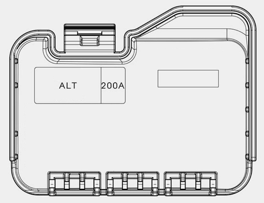
WARNING: Terminal and harness assignments for individual connectors will vary depending on vehicle equipment level, model, and market.