
MG 6 – fuse box diagram
Year of production:
Location
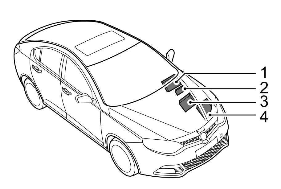
- Passenger Compartment Fuse Box (located behind the glove box)
- Auxiliary Fuse Box (located on the left side of the bulkhead in engine compartment)
- Battery Top Fuse Box (located on the battery)
- Engine Compartment Fuse Box (located in the engine compartment)
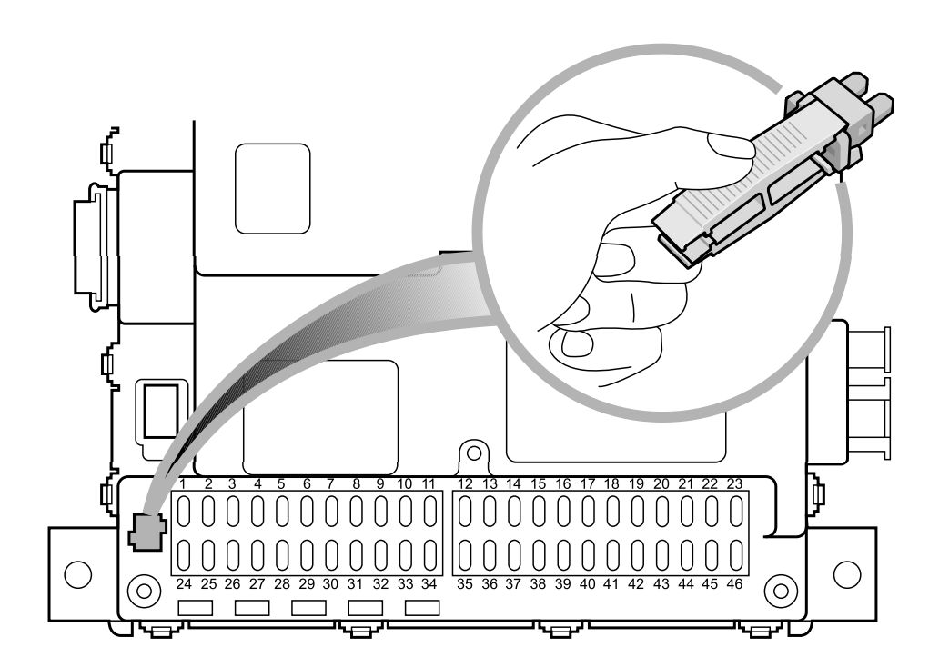
Passenger Compartment Fuse Box
| No. |
А |
Function |
| F1 | 15 | Spare |
| F2 | 15 | Front Power Socket |
| F3 | 10 | Reverse Lamps, Interior Mirror, Camera |
| F4 | 15 | Spare |
| F5 | 5 | Heated Mirror |
| F6 | 10 | Inertia Switch |
| F7 | 15 | Rear Accessory Socket |
| F8 | 30 | Power Supply – Window Lift Front – LH |
| F9 | 5 | Switch – Reverse Lamps, Switch – Master Light, Motor – Headlamp Levelling, AFS System, Passenger Airbag ON/OFF Indicator |
| F10 | 20 | Headlamp Main Beams |
| F11 | — | — |
| FI2 | 5 | Side Lamp – LH, Tail Lamp – LH, Rear Number Plate Lamps |
| F13 | 5 | Switch – EPB |
| F14 | 5 | Switch – Steering Wheel Remote |
| FI5 | 20 | ESCL ECU |
| FI6 | 30 | Pump – Windscreen Wash |
| F17 | 30 | Power Supply – Passenger Seat |
| FI8 | 15 | Horns |
| FI9 | 30 | Heated Seat – Front |
| F20 | 20 | Headlamp Dipped Beam – RH |
| F2I | 30 | Power Supply – Driver Seat |
| F22 | 5 | A/C Control Panel, Heated Seat – Front |
| F23 | 30 | Power Supply – Window Lift Rear – LH |
| F24 | 30 | Power Supply – Window Lift Front – RH |
| F2S | 15 | Spare |
| F26 | 25 | Heater Rear Window |
| F27 | 5 | Switch – Ignition |
| F28 | 5 | Spare |
| F29 | 15 | Spare |
| F30 | 15 | Spare |
| F3I | 25 | Passenger Door Locks, Rear Door Locks |
| F32 | 20 | Headlamp Dipped Beam – LH |
| F33 | — | — |
| F34 | — | — |
| F35 | 10 | Spare |
| F36 | 5 | Side Lamp – RH, Tail Lamp – RH |
| F37 | 5 | Diagnostic Socket |
| F38 | 5 | Lamp – Glovebox |
| F39 | 10 | Driver Door Locks, Motor – Fuel Flap Release, Tailgate Release Motor Relay, Motor – Tailgate Release |
| F40 | 15 | Spare |
| F41 | 10 | Rear Fog Lamps |
| F42 | 10 | Airbag ECU |
| F43 | 20 | Spare |
| F44 | 5 | Interior Mirror, Rain Sensor, PDC ECU |
| F45 | 10 | Multifunction Control Switch, Master Light Switch, Driver Door Switch Pack, Navigation Display Power |
| F46 | 30 | Power Supply – Window Lift Rear – RH |
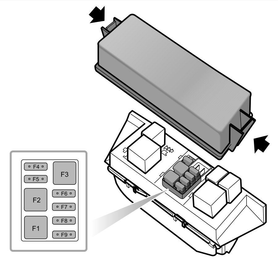
Auxiliary Fuse Box
| No. |
А |
Function |
| F1 | 30 | DC/DC Convertor |
| F2 | 30 | Relay – Electric Water Heater 1, Electric Water Heater Element 1 |
| F3 | 30 | Headlamp Wash System |
| F4 | 20 | Relay – Fuel Heater, Fuel Heater |
| F5 | 20 | AFS System |
| F6 | 5 | Interior Lamp – Front, Interior Lamp – Rear, Lamp – Vanity Mirrors |
| F7 | 15 | Entertainment System |
| F8 | 10 | A/C Control Panel, Fresh/Recycle Motor |
| F9 | 10 | Instrument Pack |
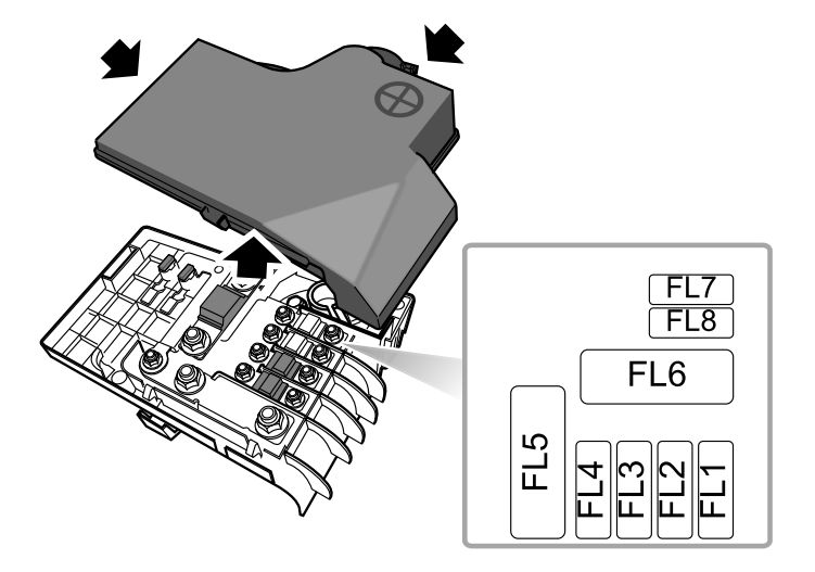
Battery Top Fuse Box
| No. |
А |
Function |
| FL1 | 30 | EPB ECU |
| FL2 | 30 | EPB ECU |
| FL3 | 125 | Auxiliary Fuses 1, 2, 3, 4, 5, Relay – Electric Water Heater 2, Electric Water Heater Element 2 |
| FL4 | 60 | Control Unit Glow Plug |
| FL5 | — | — |
| FL6 | 450 | Motor – Starter |
| FL7 | 5 | EBS |
| FL8 | 30 | Relay – Electric Water Heater 3, Electric Water Heater Element 3 |
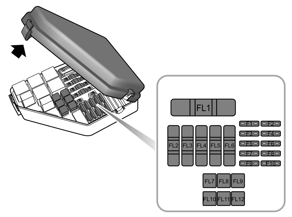
Engine Compartment Fuse Box
| No. |
А |
Function |
| F1 | 15 | Sensor – Wide Band, Control Unit – Glow Plug, ECU – Engine, Switch – Clutch Pedal |
| F2 | 20 | Power Supply – Fuel Filter, Bypass – EGR Cooling, Actuator – Variable Swirl, Valve – Throttle Actuator, Sensor – Hot Film Airmass, Variable Geometry Turbo Controller |
| F3 | 10 | Pump – High Pressure, Valve – Pressure Control |
| F4 | 15 | Cooling Fan, Relay – Starter, Relay – Fuel Heater, Master Switch – Start Stop, Relay – Electric Water Heater 1, Relay – Electric Water Heater 3, Switch – Neutral, ECU – Engine |
| F5 | 10 | Spare |
| F6 | 15 | Day Running Lamps |
| F7 | 30 | Lamp – Direction Indicator Front – LH, Lamp – Direction Indicator Rear – LH, Lamp – Side Repeater – LH, Relay – Reverse Lamp, Relay – Position Lamp, Lamp – Rear Brake – LH, Passenger Compartment Fuses 3, 12, 36 |
| F8 | 20 | Passenger Compartment Fuse 7 |
| F9 | 10 | Relay – Compressor Clutch – Air Conditioning, Compressor – Air Conditioning Clutch |
| F10 | 30 | Relay – Wiper 1, Relay – Wiper 2 |
| FL1 | 200 | Alternator, Engine Compartment Fuse Links 2, 7,10 and Fuses 5, 8, 9 |
| FL2 | 60 | Passenger Compartment Fuses 1, 6, 9, 22, 24, 25, 27, 28, 42, Relay – Switched |
| FL3 | 50 | Relay – Horn, Rotary Coupler, Passenger Compartment Fuses 16, 17, 18 |
| FL4 | 50 | Cooling Fan |
| FL5 | 100 | Relay – Dipped Beam, Relay – Rear Fog Lamp, Passenger Compartment Fuses 19, 20, 21, 23, 30, 35, 37, 39, 40, 41, 43, 45, 46 |
| FL6 | 70 | EHPAS ECU & Pump |
| FL7 | 40 | Relay – Starter, Starter Motor |
| FL8 | 40 | SCS ECU (Pump) |
| FL9 | 50 | Passenger Compartment Fuses 2, 5, 10, 13, 14, 15, 26, 38, 44, Relay – Heated Rear Screen, Relay – Main Beam, Relay – Auxiliary |
| FL10 | 40 | Relay – Blower, Motor – Blower, A/C Control Panel |
| FL11 | 25 | SCS ECU (Valve) |
| FL12 | 50 | Relay – Dipped Beam, Lamp – Direction Indicator Front – RH, Lamp – Direction Indicator Rear – RH, Lamp – Side Repeater – RH, Lamps – Rear Brake – RH, Passenger Compartment Fuses 8, 31, 32 |
WARNING: Terminal and harness assignments for individual connectors will vary depending on vehicle equipment level, model, and market.