Ford F-250 (2011 – 2016) – fuse box diagram
Year of production: 2011, 2012, 2013, 2014, 2015, 2016
Passenger Compartment Fuse Box
The fuse panel is located in the passenger’s footwell.
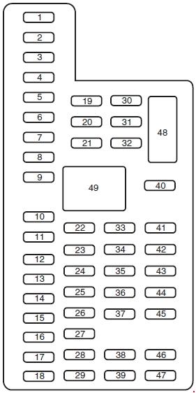
| Number | Ampere rating [A] | Description |
| 1 | 30 | — |
| 2 | 15 | Upfitter relay #4 |
| 3 | 30 | Passenger smart window motor |
| 4 | 10 | Telescoping mirror switch, Interior lights, Hood lamp |
| 5 | 20 | Moon roof |
| 6 | 5 | Driver seat module |
| 7 | 7,5 | Driver seat switch, Driver lumbar motor |
| 8 | 10 | Power mirror switch |
| 9 | 10 | Upfitter relay #3 |
| 10 | 10 | Run/accessory relay, Customer access feed |
| 11 | 10 | Instrument cluster |
| 12 | 15 | Interior lighting, Lighted running board lamps |
| 13 | 15 | Right turn signals and brake lamps, Right trailer tow stop turn relay |
| 14 | 15 | Left turn signals and brake lamps, Left trailer tow stop turn relay |
| 15 | 15 | High-mounted stop lamps, Backup lamps, Trailer tow backup relay, Reverse signal interior mirror |
| 16 | 10 | Right low beam headlamp |
| 17 | 10 | Left low beam headlamp |
| 18 | 10 | Keypad illumination, Passive anti-theft indicator (PATS), Passive anti-theft transceiver, Powertrain control module (PCM), Brake shift interlock |
| 19 | 20 | Subwoofer, Amplifier (’13-’16) |
| 20 | 20 | Power door locks |
| 21 | 10 | Brake on/off switch |
| 22 | 20 | Horn |
| 23 | 15 | — |
| 24 | 15 | Steering wheel control module, Diagnostic connector, Satellite radio module, Power fold mirror relay, Remote keyless entry, Electronic finish panel |
| 25 | 15 | — |
| 26 | 5 | Steering wheel control module |
| 27 | 20 | ’11-’12: Amplifier |
| 28 | 15 | Ignition switch |
| 29 | 20 | SYNC®, GPS module, Radio faceplate |
| 30 | 15 | Parking lamp relay, Trailer tow parking lamp relay |
| 31 | 5 | Trailer brake controller (brake signal), Customer access |
| 32 | 15 | Moonroof, Auto-dimming mirrors, Power inverter, Driver and passenger door lock switch illumination, Driver and passenger smart window motor, Passenger window switch, Rear heated seat switch illumination, Telescoping mirror switch |
| 33 | 10 | Restraint control module |
| 34 | 10 | Heated steering wheel module, Rear heated seat module |
| 35 | 5 | Select shift switch, Reverse park aid module, Trailer brake control module |
| 36 | 10 | Fuel tank select switch |
| 37 | 10 | PTC heater |
| 38 | 10 | Radio faceplate (AM/FM base radio) |
| 39 | 15 | High beam headlamps |
| 40 | 10 | Parking lamps (in mirrors), Roof marker lamps |
| 41 | 7,5 | Passenger airbag deactivation indicator |
| 42 | 5 | — |
| 43 | 10 | Wiper relay |
| 44 | 10 | Upfitter switches |
| 45 | 5 | — |
| 46 | 10 | Climate control |
| 47 | 15 | Fog lamps, Fog lamp indicator (in the switch) |
| 48 | 30 | Circuit Breaker: Power windows switch, Power rear sliding window switch, Moonroof switch |
| Relay | ||
| 49 | Delayed accessory | |
Engine Compartment Fuse Box
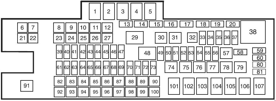
| Number | Ampere rating [A] | Description |
| 6 | — | — |
| 7 | 50 | Rear window defroster, Heated mirrors |
| 8 | 30 | Passenger seat |
| 9 | 30 | Driver seat |
| 10 | 40 | ’15-’16: Trailer tow |
| 11 | — | — |
| 12 | 30 | Driver smart window motor |
| 13 | — | — |
| 14 | — | — |
| 15 | — | Diode: Diesel: Fuel pump |
| 16 | — | — |
| 17 | 15 | Heated mirror |
| 18 | — | — |
| 19 | — | — |
| 20 | — | — |
| 21 | — | — |
| 22 | 30 | Trailer tow electric brake |
| 23 | 40 | Blower motor |
| 24 | — | — |
| 25 | 30 | Wipers |
| 26 | 30 | Trailer tow park lamps |
| 27 | 25 | Diesel: Urea heaters |
| 28 | — | Buss bar |
| 32 | — | — |
| 33 | 15 | Vehicle power (VPWR) 1 |
| 34 | 15 | Diesel: Vehicle power (VPWR) 2 |
| 20 | Gasoline: Vehicle power (VPWR) 2 | |
| 35 | 10 | Vehicle power (VPWR) 3 |
| 36 | 15 | Diesel: Vehicle power (VPWR) 4 |
| 20 | Gasoline: Vehicle power (VPWR) 4 | |
| 37 | 10 | Diesel: Vehicle power (VPWR) 5 |
| 39 | 10 | 4×4 hub lock |
| 40 | 15 | 4×4 electronic lock |
| 41 | — | — |
| 42 | 20 | Rear heated seats |
| 43 | — | — |
| 44 | — | — |
| 45 | 10 | Run/start relay coil |
| 46 | 10 | Diesel: Transmission control module (TCM) keep-alive power |
| 47 | 10 | A/C clutch feed |
| 49 | 10 | Rearview camera system |
| 50 | 10 | Blower motor relay coil |
| 51 | — | — |
| 52 | 10 | Electronic control module (ECM), Powertrain control module (PCM), Transmission control module run/start (TCM) |
| 53 | 10 | 4×4 module |
| 54 | 10 | Anti-lock brake system (ABS) run/start |
| 55 | 10 | Rear window defroster coil, Battery charge coil |
| 56 | 20 | Passenger compartment fuse panel run/start feed |
| 58 | — | — |
| 59 | — | — |
| 60 | — | — |
| 61 | — | – |
| 62 | — | — |
| 63 | — | — |
| 64 | — | — |
| 65 | — | — |
| 66 | 20 | Fuel pump |
| 67 | — | — |
| 68 | 10 | Fuel pump relay coil |
| 69 | — | — |
| 70 | 10 | Trailer tow backup lamp |
| 71 | 10 | Gasoline: Cannister vent |
| 72 | 10 | PCM/ECM relay coil feed keep-alive power |
| 73 | — | — |
| 80 | — | — |
| 81 | — | — |
| 82 | 20 | Auxiliary power point #2 |
| 83 | 20 | Auxiliary power point #1 |
| 84 | 30 | 4×4 shift motor |
| 85 | 30 | Heated/cooled seats |
| 86 | 25 | ABS coil feed |
| 87 | 20 | Auxiliary power point #5 |
| 88 | 20 | ’13-’16: Auxiliary power point #6 |
| 89 | 40 | Starter motor |
| 90 | 25 | Trailer tow battery charge |
| 91 | — | — |
| 92 | 20 | Auxiliary power point #4 |
| 93 | 20 | Auxiliary power point #3 |
| 94 | 25 | Upfitter #1 |
| 95 | 25 | Upfitter #2 |
| 96 | 50 | ABS pump |
| 97 | 40 | Invertor |
| 98 | — | — |
| 99 | 40 | ’13-’16: Instrument panel power inverter |
| 100 | 25 | ’11-’14: Trailer tow turn signals |
| Relay | ||
| 1 | Blower motor | |
| 2 | — | |
| 3 | Diesel: Urea heaters | |
| 4 | — | |
| 5 | Rear window defroster, Heated mirrors | |
| 29 | Trailer tow park lamps | |
| 30 | A/C clutch | |
| 31 | Wipers | |
| 38 | Diesel: Powertrain control module (PCM) Gasoline: Electronic control module (ECM) |
|
| 48 | Run/start | |
| 57 | Fuel pump | |
| 74 | Trailer tow left-hand stop/turn | |
| 75 | Trailer tow right-hand stop/turn | |
| 76 | Backup lamp | |
| 77 | — | |
| 78 | — | |
| 79 | — | |
| 101 | Starter | |
| 102 | Trailer tow battery charge | |
| 103 | — | |
| 104 | — | |
| 105 | — | |
| 106 | — | |
| 107 | — | |
WARNING: Terminal and harness assignments for individual connectors will vary depending on vehicle equipment level, model, and market.