Ford F53 (1997) – wiring diagrams – fuse panel
Year of productions: 1997
Fuse panel
Engine compartment
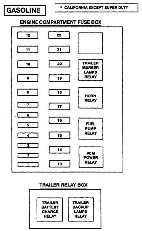
| Fuse position | Ampere rating [A] | Circuits protected |
| 1 | 20 | Radio |
| 2 | — | — |
| 3 | 30 | Hom Relay, Daytime Running Lamps, Headlamp Flash-to-Pass |
| 4 | 25 | Trailer Marker Lamps Relay, Trailer Backup Lamps Relay |
| 5 | 15 | Heated Oxygen Sensor (H02S), Backup Lamps, Trailer Battery Charge Relay, Daytime Running Lamps, Speed Control |
| 6 | 10 (5*) | Trailer Right Stop/Turn Lamps |
| 7 | 10 (5*) | Trailer Left Stop/Turn Lamps |
| Maxi – Fuse position | Ampere rating [A] | Circuit protected |
| 8 | — | — |
| 9 | 30 | PCM Power Relay, Powertrain Control Module (PCM) |
| 10 | 20 | See Fuses 15 and 18. Starter Relay |
| 11 | — | — |
| 12 | 20 | Diode Current Flows From Fuse 22 to PCM Power Relay |
| 13 | 50 | See fuse 5, 9 and 13 |
| 14 | — | — |
| 15 | 50 | See fuse 1 and 7 and fuse 5 |
| 16 | 20 | Fuse Pump Relay |
| 17 | 50 | Generator Charge indicator, lnstrument Cluster See Fuses 2, 6, 11, 17 and Maxi-fuse 22, see Circuit Breaker 14 |
| 18 | 30 | Trailer Banery Charge Relay |
| 19 | 40 | Main Light Switch, Headlamps (Fog Lamp, Indicator Lamp, Fog Lamp Relay Coil (lighting Only)) |
| 20 | 50 | See fuse 4, 8 and 16, see Circuit Breaker 12 |
| 21 | 30 | Trailer Electronic Brake Control unit |
| 22 | 20 | Ignition system, PCM Power Relay Coil |
Instrument panel
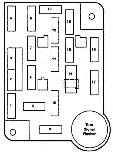
| Fuse position | Ampere rating [A] | Circuit protected |
| 1 | 30 | Air Conditioner/Heater |
| 2 | 30 | Interval wiper/washer |
| 3 | 3 | Idle position wwitch (Oiesel Only) |
| 4 | 15 | Elcterior Lamps, Trailer Marker Lamps Relay, Warning Chime, Instrument Illumination, Keyless Entry, Ami-Theft, Trailer Brake Control Unit |
| 5 | — | — |
| 6 | 15 | Fuel Tank Selector (Diesel Only), Anti-Theft, Keyless Entry, Air Conditioner/Compressor Clutch |
| 7 | 15 | Tum Lamps |
| 8 | 15 | Courtesy Lamps, Engine Compartment Lamp, Power Mirrors, Vanity Mirrors, Speedometer Memory, Warning Chime, Keyless Entry |
| 9 | 25 | Power Point |
| 10 | 4 | Instrument Illumination |
| 11 | 4 | Radio |
| 12 | 20 c.b. | Power Door, Lock, Power Lumbar, Anti-Theft, Keyless Entry |
| 13 | 15 | Stop and Hazard Lamps, Stop Sense For, Anti·lock Brakes, Speed Control, PCM, Shift Lock |
| 14 | 20 c.b. | Power Windows |
| 15 | 20 | Anti-lock Brakes |
| 16 | 15 | Cigar Lighter, Data Link Connector (Diesel Only) |
| 17 | 10 | Trans Control Indicator Lamp and Switch, Brake Fluid Level Switch, Warning Chime, Diesel Warning Lamps Display, Fuel Water Switch, Low Vacuum Warning Switch, instrument Cluster, Switch Lamps |
| 18 | 10 | Speedometer, Day/Night Mirror, Auxiliary Powertrain Control (Diesel Only), Speed Control (Diesel Only), Shift Lock |
| Fuse value amps | Color code |
| 3 | Violet |
| 4 | Pink |
| 5 | Tan |
| 10 | Red |
| 15 | Light Blue |
| 20 | Yellow |
| 25 | Natural |
| 30 | Light Green |
WARNING: Terminal and harness assignments for individual connectors will vary depending on vehicle equipment level, model, and market.