
FUSE BOX DIAGRAMS & RELAY INFORMATION
Infiniti I30 (A33; 2000–2001) – Fuse Box Locations and Diagrams
Explore the fuse box diagrams, fuse assignments, relay locations and electrical component layouts for the second-generation Infiniti I30 (A33), covering the 2000 and 2001 model years.
This guide includes the passenger compartment fuse box, passenger compartment relay box, engine compartment fuse box, two engine compartment relay boxes and major electrical control units.
Use the searchable fuse tables below to identify the fuses for the cigarette lighter, power socket, fuel pump, headlights, windshield wipers, blower motor, audio system and other electrical components.
Vehicle Information
- Vehicle
- Infiniti I30
- Generation
- Second generation (A33)
- Model years
- 2000–2001
- Body
- 4-door luxury sedan
- Platform
- Nissan A33
- Drivetrain
- Front-wheel drive (FWD)
- Engine
- 3.0L VQ30DE V6 gasoline
- Transmission
- 4-speed automatic
- Market
- North America
- Assembly
- Japan
Fuse Box Locations
The Infiniti I30 (A33) has a passenger compartment fuse box and an engine compartment fuse box. Additional relays are located inside the vehicle and in two relay boxes in the engine compartment.
The passenger compartment fuse box protects interior electrical systems, including the cigarette lighter, power socket, windshield wipers, interior lighting and electronic control modules. The engine compartment fuse box contains fuses and high-current fusible links for the headlights, engine management system, cooling fans, blower motor and other major circuits.
Passenger Compartment
The following diagram identifies the locations of the passenger compartment fuse box, control modules, relays and circuit breakers.
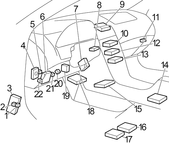
Passenger Compartment Component Identification
| No. | Component / description |
|---|---|
| 1 | Fuel Pump Relay |
| 2 | Rear Window Defogger Relay |
| 3 | ABS Control Unit or ABS/TCS Control Unit (2000–2001) |
| 4 | Super Multiple Junction (SMJ) |
| 5 | Circuit Breaker |
| 6 | Fuse Box |
| 7 | Smart Entrance Control Unit |
| 8 | Nissan Anti Theft System (NATS) Immobilizer |
| 9 | Monitor (2001) |
| 10 | Navigation Control Unit (2001) |
| 11 | Blower Motor Relay |
| 12 | Audio Unit |
| 13 | A/C Auto Amplifier |
| 14 | Air Bag Diagnosis Sensor Unit |
| 15 | Transmission Control Module (TCM) |
| 16 | Seat Control Unit / Memory Seat Unit |
| 17 | Not specified for 2000–2001; source assigns VDC/TCS/ABS Control Unit to 2002–2004 |
| 18 | Engine Control Module (ECM) |
| 19 | Headlamp Battery Saver Control Unit |
| 20 | Combination Flasher Unit |
| 21 | Power Window Relay (2000) |
| 22 | Power Window Relay (2001) |
Diagram note: Position 17 is retained to preserve the numbering of the original combined diagram, but its listed function applies to the later 2002–2004 reference.
Passenger Compartment Fuse Box
The passenger compartment fuse box contains 31 numbered positions. These protect the cigarette lighter, power socket, fuel pump, windshield wipers, heated seats, lighting systems and various electronic control modules.
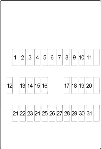
| No. | Amps | Protected circuit / description |
|---|---|---|
| 1 | 10A | Smart Entrance Control Unit, Auto Light Sensor, Lighting Switch, Turn Signal and Hazard Warning Lamps, Combination Meter, Audio Unit, CD Auto Changer, Steering Switch, Antenna Amplifier, Door Mirror Remote Control Switch, Telephone, Remote Keyless Entry System, Theft Warning System, Navi Control Unit, Monitor |
| 2 | 15A | Stop Lamp Switch, Automatic Speed Control Device (ASCD), Transmission Control Module (TCM), ABS |
| 3 | 15A | Trunk Lid Opener Actuator, Fuel Lid Opener Actuator |
| 4 | 20A | Rear Window Defogger Relay |
| 5 | 15A | Hazard Switch (Combination Flasher) |
| 6 | 15A | Front Fog Lamp Relay |
| 7 | 20A | Rear Window Defogger Relay, A/C Auto Amplifier, Door Mirror Defogger Relay |
| 8 | 15A | Air Fuel Ratio Sensors, Heated Oxygen Sensors |
| 9 | 10A | Front Heated Seats |
| 10 | 10A | Smart Entrance Control Unit, Heated Steering Relay, Auto Light Sensor, Lighting Switch, Turn Signal and Hazard Warning Lamps, Interior Lamp, Spot Lamp, Vanity Mirror Lamps, Trunk Room Lamp, Ignition Key Hole Illumination, Front Step Lamps, Front Power Window Switch, Warning Chime, Rear Window Defogger Relay, A/C Auto Amplifier, Sunroof, Telephone, Automatic Drive Positioner, Power Window, Remote Keyless Entry System, Theft Warning System, Infiniti Vehicle Immobilizer System (IVIS), Navi Control Unit |
| 11 | 10A | Transmission Control Module (TCM), Speed Sensor, A/T Fluid Temperature Sensor, Powertrain Revolution Sensor |
| 12 | 10A | Combination Meter, Clock, Telephone, Automatic Drive Positioner, Memory Seat Switch, Theft Warning System, Infiniti Vehicle Immobilizer System (IVIS) |
| 13 | 10A | Smart Entrance Control Unit, Heated Steering Switch, Auto Light Sensor, Lighting Switch, Turn Signal and Hazard Warning Lamps, Interior Lamp, Spot Lamp, Vanity Mirror Lamps, Trunk Room Lamp, Ignition Key Hole Illumination, Front Step Lamps, Front Power Window Switch, Key Switch, Warning Chime, Door Mirror Defogger Relay, Sunroof, Automatic Drive Positioner, Power Window, Power Door Lock, Remote Keyless Entry System, Theft Warning System, Infiniti Vehicle Immobilizer System (IVIS) |
| 14 | — | Not assigned |
| 15 | — | Not assigned |
| 16 | 15A | Power Socket |
| 17 | 10A | Injectors, Fuel Pump Relay |
| 18 | 10A | Air Bag Diagnosis Sensor Unit |
| 19 | 10A | Rear Heated Seats |
| 20 | 15A | Cooling Fan, Start Signal, EVAP Canister Vent Control Valve, Vacuum Cut Valve Bypass Valve, Variable Induction Air Control System, Infiniti Vehicle Immobilizer System (IVIS) |
| 21 | 10A | Daytime Light Control Unit, Seat Control Unit, Start Signal |
| 22 | 15A | Cigarette Lighter |
| 23 | 10A | Rear Sunshade Unit |
| 24 | — | Not assigned |
| 25 | 20A | Front Wiper Motor, Front Washer Motor, Front Wiper Switch |
| 26 | 10A | Hazard Switch (Combination Flasher), Cornering Lamp Relay |
| 27 | — | Not assigned |
| 28 | 10A | Daytime Light Control Unit, A/C Auto Amplifier |
| 29 | 15A | Fuel Pump Relay, Fuel Pump Control Module (FPCM) |
| 30 | 10A | Combination Meter, Daytime Light Control Unit, Alternator, Park/Neutral Position Switch (Back-Up Lamps), Compass, Auto Anti-Dazzling Inside Mirror, Automatic Drive Positioner, Navi Control Unit |
| 31 | 10A | VDC/TCS/ABS (combined source chart; applicability to 2000–2001 not confirmed) |
No matching fuses in this table.
Important: The original reference combines 2000–2004 vehicles. Fuse No. 31 is described as protecting VDC/TCS/ABS, while the component-location diagram assigns the VDC/TCS/ABS control unit specifically to 2002–2004. Its applicability to the 2000–2001 I30 should therefore be verified.
Passenger Compartment Relay Box
The passenger compartment relay box contains relays for the power socket, ignition and accessory circuits.
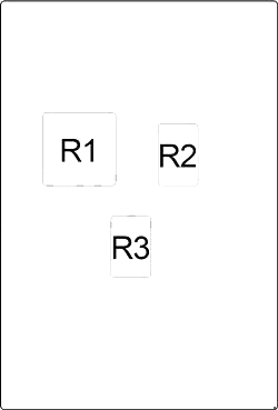
| No. | Relay / function |
|---|---|
| R1 | Power Socket |
| R2 | Ignition |
| R3 | Accessory |
Additional Passenger Compartment Components
The following diagram identifies additional electrical components, including the trunk and fuel lid opener actuators, rear sunshade unit and BOSE amplifier.
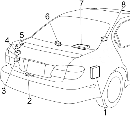
| No. | Model years | Component / description |
|---|---|---|
| 1 | 2000–2001 | Infiniti Communicator (IVCS) Unit |
| 2 | Source chart | Trunk Lid Opener Actuator |
| 3 | 2000 | Dropping Resistor |
| 4 | 2000 | Fuel Pump Control Module (FPCM) |
| 5 | Source chart | Fuel Lid Opener Actuator |
| 6 | Source chart | Rear Sunshade Unit |
| 7 | Source chart | BOSE Amplifier |
Engine Compartment
The engine compartment contains the main fuse box, two relay boxes, front wiper motor, ABS/TCS actuator and other electrical components.

| No. | Component / description |
|---|---|
| 1 | Fuse Box |
| 2 | Relay Box No. 2 |
| 3 | Hood Switch |
| 4 | Daytime Light Control Unit |
| 5 | Relay Box No. 1 |
| 6 | Front Wiper Motor |
| 7 | ABS/TCS Actuator |
Engine Compartment Fuse Box
The engine compartment fuse box contains fuses and high-current fusible links for the blower motor, headlights, engine management system, cooling fans, ABS/TCS and other major electrical circuits.
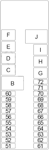
| No. | Amps | Protected circuit / description |
|---|---|---|
| 51 | 15A | Blower Motor |
| 52 | 15A | Blower Motor |
| 53 | — | Not assigned |
| 54 | 20A | Left Headlamp (Low Beam), Smart Entrance Control Unit, Front Fog Lamp Relay, Front Fog Lamp Switch |
| 55 | 20A | Right Headlamp (Low Beam), Smart Entrance Control Unit |
| 56 | 15A | Audio Unit, BOSE Amplifier, CD Auto Changer, Steering Switch, Navi Control Unit, Monitor, Infiniti Communicator (IVCS) |
| 57 | 10A | Horn Relay, Infiniti Communicator (IVCS), Theft Warning System, Automatic Speed Control Device (ASCD), Multi-Remote Control |
| 58 | 15A | Engine Control Module (ECM), Ignition Coils, EVAP Canister Purge Volume Control Solenoid Valve, Intake Valve Timing Control Solenoid Valve |
| 59 | 15A | Engine Control Module (ECM), Infiniti Vehicle Immobilizer System (IVIS), Mass Air Flow Sensor, Crankshaft Position Sensor, EVAP Canister Purge Volume Control Solenoid Valve, Intake Valve Timing Control Solenoid Valve, Ignition Signal, Front Electronic Controlled Engine Mount, Rear Electronic Controlled Engine Mount, Camshaft Position Sensor |
| 60 | 10A | Tail Lamp Relay (Lighting Switch, Side Marker Lamps, Parking Lamps, Tail Lamps, License Lamps, Stop Lamps, Smart Entrance Control Unit, Cornering Lamp Relay, Glove Box Lamp, Warning Chime, Illumination Control Switch, Illumination: Ashtray, Automatic Transmission Device, Clock, Audio Unit, Hazard Switch, Door Mirror Remote Control Switch, Heated Steering Switch, Navi Control Unit, Rear Sunshade Switch, TCS On/Off Switch, A/C Auto Amplifier, VDC Off Switch, Combination Meter) |
| 61 | 10A | Vehicle Security Horn Relay |
| 62 | — | Not assigned |
| 63 | 15A | Engine Control Module (ECM) |
| 64 | — | Not assigned |
| 65 | — | Not assigned |
| 66 | 10A | A/C Relay |
| 67 | 15A | Woofer |
| 68 | 15A | Left Headlamp (High Beam), Daytime Light Control Unit |
| 69 | 15A | Right Headlamp (High Beam), High Beam Indicator, Daytime Light Control Unit |
| 70 | 10A | Alternator |
| 71 | — | Not assigned |
| 72 | 10A | Heated Steering Relay, Heated Steering Switch |
No matching fuses in this table.
High-Current Fuses and Fusible Links
The following high-current fuses and fusible links protect the main power distribution circuits.
| No. | Amps | Protected circuit / description |
|---|---|---|
| B | 80A | Accessory Relay (Fuses 22 and 23), Ignition Relay (Fuses 9, 9, 10 and 11), Blower Motor Relay (Fuse 16), Fuses 12 and 13 |
| C | 40A | Ignition Switch |
| D | 40A | ABS/TCS |
| D | 50A | VDC/TCS/ABS – later configuration; applicability to 2000–2001 not confirmed |
| E | 40A | ABS/TCS |
| E | 50A | VDC/TCS/ABS – later configuration; applicability to 2000–2001 not confirmed |
| F | — | Not assigned |
| G | 40A | Cooling Fan |
| H | 40A | Cooling Fan |
| I | 40A | Circuit Breaker (Power Window, Sunroof, Power Seat, Power Door Lock, Remote Keyless Entry System) |
| J | 80A | Ignition Relay (Fuses 25, 26, 28, 29, 30 and 31), Fuses 2, 3, 4, 5, 6 and 7 |
Important: The original reference lists 40A ABS/TCS and 50A VDC/TCS/ABS variants for fusible links D and E. For the 2000–2001 I30, the ABS/TCS control unit is identified in the passenger compartment diagram. Verify the correct installed system and fusible link rating before replacement.
Engine Compartment Relay Box No. 1
Relay Box No. 1 contains relays for the headlights, exterior lighting, horn, air conditioning, heated mirrors and vehicle security system.
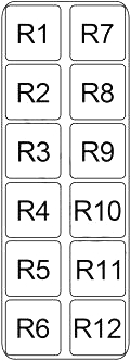
| No. | Model years | Relay / function |
|---|---|---|
| R1 | Source chart | Door Mirror Defogger |
| R2 | Source chart | Tail Lamp |
| R3 | Source chart | Cornering Lamp |
| R4 | Source chart | Right Headlamp |
| R5 | Source chart | Horn |
| R6 | Source chart | Air Conditioner |
| R7 | Source chart | Front Fog Lamp |
| R8 | 2001 | Vehicle Security Horn (No. 2) |
| R9 | Source chart | Vehicle Security Horn |
| R10 | 2000 | Multi-Remote Control |
| R11 | Source chart | Left Headlamp |
| R12 | Source chart | Not assigned |
Engine Compartment Relay Box No. 2
Relay Box No. 2 contains relays for the cooling fans, engine control module, starting system and ABS.
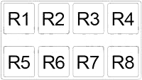
| No. | Model years | Relay / function |
|---|---|---|
| R1 | Source chart | Cooling Fan (No. 3) |
| R2 | Source chart | Park/Neutral Position |
| R3 | Not assigned in source for 2000–2001 | Throttle Control Motor – 2002–2004 reference only |
| R4 | 2000–2001 | ABS Solenoid Valve |
| R5 | Source chart | Engine Control Module (ECM) |
| R6 | Source chart | Cooling Fan (No. 2) |
| R7 | 2000–2001 | ABS Motor |
| R8 | Source chart | Cooling Fan (No. 1) |
Diagram note: Relay position R3 is retained to match the original diagram. Its listed throttle control motor function applies specifically to 2002–2004 and is not confirmed for the 2000–2001 I30.
Frequently Asked Questions
Where is the fuse box located in the Infiniti I30 (2000–2001)?
The second-generation Infiniti I30 has a passenger compartment fuse box and an engine compartment fuse box. Additional relays are located in the passenger compartment and in two engine compartment relay boxes.
Which fuse controls the cigarette lighter?
Passenger compartment fuse No. 22 (15A) protects the cigarette lighter according to the supplied fuse chart.
Which fuse controls the power socket?
Passenger compartment fuse No. 16 (15A) protects the power socket. The passenger compartment relay box also contains the power socket relay (R1).
Which fuse protects the fuel pump?
Passenger compartment fuse No. 29 (15A) protects the fuel pump relay and Fuel Pump Control Module (FPCM) according to the supplied combined reference. Fuse No. 17 (10A) is also associated with the fuel pump relay and injectors.
Which fuse controls the windshield wipers?
Passenger compartment fuse No. 25 (20A) protects the front wiper motor, washer motor and wiper switch.
Which fuses protect the blower motor?
Engine compartment fuses No. 51 and No. 52 (15A each) protect the blower motor.
Which fuses protect the headlights?
Engine compartment fuses No. 54 and No. 55 (20A each) protect the left and right low-beam headlight circuits. Fuses No. 68 and No. 69 (15A each) protect the high-beam circuits.
Which fuse protects the audio system?
Engine compartment fuse No. 56 (15A) protects the audio unit, BOSE amplifier, CD auto changer and related equipment. Fuse No. 67 (15A) protects the woofer.
Are the Infiniti I30 and I35 fuse box diagrams identical?
No. Although both models use the A33 platform, they have different engines and some electrical systems differ. The Infiniti I30 covers the 2000–2001 model years, while the Infiniti I35 covers 2002–2004.
Can I replace a blown fuse with a higher-amperage fuse?
No. Always replace a blown fuse with one of the same specified amperage and type. A higher-rated fuse may damage the electrical system or create a fire hazard.
Disclaimer: This guide is based on a combined electrical reference covering Infiniti I30 and I35 vehicles from 2000–2004. Year-specific components have been identified where the original source provides that information. Other fuse and relay assignments may vary depending on model year, equipment and market. Terminal and harness assignments for individual connectors may also differ. Always verify fuse ratings and circuit assignments against the vehicle’s fuse box cover or official service documentation before performing electrical repairs.